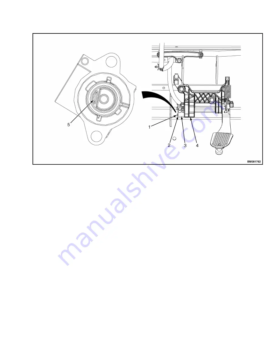
1. PAN-HEAD SCREW
2. LOCKWASHER
3. THROTTLE POSITION SENSOR
4. THROTTLE BASE
5.
D
SHAPED THROTTLE SHAFT END
Figure 13. Throttle Position Sensor
Install
1.
Insert new throttle position sensor into opening
on throttle base plate. See Figure 13.
2.
Rotate sensor so that the D shaped throttle
shaft end slides into throttle position sensor.
See Figure 13.
3.
Rotate sensor counterclockwise until locating
pin on sensor lines up with hole in throttle base
plate.
4.
Install throttle position sensor onto throttle
base using two lockwashers and two pan head
screws. Tighten screws to 2.25 N•m (20 lbf in).
5.
Install throttle base plate, pedal assembly, and
three bolts onto cowl. Tighten bolts to 19 to
25 N•m (168 to 221 lbf in). See Figure 12.
6.
Connect throttle position sensor connector to
wiring harness as tagged during removal.
7.
Install lever bracket onto cowl. Install clevis
and retention pins, and connect levers to con-
trol valve. See Figure 11.
8.
Install kick panel and dash. See Dash Panel,
Kick Panel, and Seal Plate, Remove and Install
for installation procedures.
9.
Install upper steering column cover. See Dis-
play Switch Cluster.
10.
Connect battery and lower the hood.
11.
Adjust throttle pedal stop, see Frame
0100SRM1766 for adjustment procedure.
BRAKE FLUID LEVEL SWITCH
Remove
NOTE:
The brake fluid level switch is a component
of the brake fluid reservoir, located inside the res-
ervoir. When the switch is replaced, the reservoir
must be replaced as well.
2200 SRM 1771
Sensors and Switches
13


