background image

Inspection

6

 90 

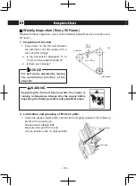
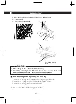
 Weekly Inspection (Every 50 Hours)

Besides the daily inspection, carry out the following inspections once a week (every 
50 hours).

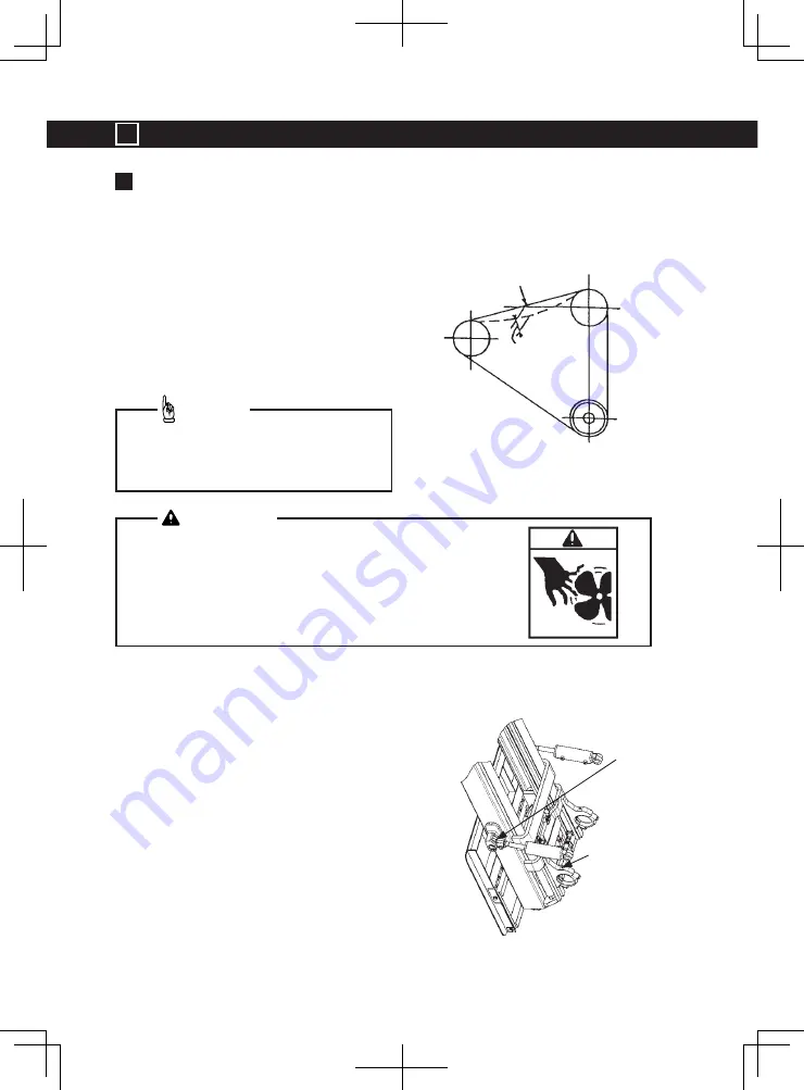
1.   Inspection of fan belt

  1.  Press down on the fan belt between 

the alternator and fan pulley with a 
force of 98 N (10kgf).

a.  Is the belt tension adequate? 11 to 

13mm (when pressed with 98 N)

b.  Is there any damage?

2.   Lubrication and greasing of lift truck parts

  1.  Clean the grease nipples with a clean cloth and apply grease to the following 

points with a grease gun.

    Grease Used: Albania EP2
    Mast trunnion and Tilt rod end
    (At one location each on right and left)

Inspecting the fan belt tension while the engine is 

running is dangerous. Always stop the engine before 

inspecting the rotating sections and peripheral areas.

 WARNING

The belt can be adjusted by moving 

the installation position of the 

alternator.

 ADVICE

98 N

(10kgf)

Alternator

Fan

11 to 13mm

Crankshaft

Lubricate

Lubricate

Summary of Contents for H1.5XT

Page 1: ...OPERATING MANUAL DO NOT REMOVE THIS MANUAL FROM THIS UNIT H1 5 1 8XT H2 0XTS H2 0 3 5XT D475 D466 ...

Page 2: ......

Page 3: ... Powershift Transmission with Monotrol Pedal Key Switch Dash Display Operator Mode Operator setting functions Safety device Levers Pedals Light Switch Steering Wheel ECO mode switch Electronic controlled engine Fuel changeover switch Dual fuel truck Return To Vertical RTV Option Truck Structure and Stability 40 Load and Truck Stability Center of Gravity Stability Range Load Center and Capacity Tab...

Page 4: ...eekly Inspection Every 50 Hours Monthly Inspection Every 200 Hours Work Items 98 Replacement of Engine Oil Replacement of Engine Oil Filter Draining of Sedimenter Diesel Bleeding Air in Fuel system Diesel Parking Brake Lever Adjustment Checking Fuses How to Start Engine when Battery Discharged How to Use Coupler Pin Changing Tires Installation Procedures Dual Drive Wheels of 2 0 3 5 ton trucks Was...

Page 5: ... of lift trucks Model of lift truck Rated capacety kg Load center mm Engine H1 5XT 1 500 500 GCT K21 Yanmar 4TNE92 H1 8XT 1 750 500 H2 0XTS 2 000 500 H2 0XT 2 000 500 GCT K21 GCT K25 Yanmar 4TNE92 Yanmar 4TNE98 H2 5XT 2 500 500 H3 0XT 3 000 500 GCT K25 Yanmar 4TNE98 H3 5XT 3 500 500 ...

Page 6: ...n the truck specifications The following marks are used in this manual to show important items related to safety etc Read this points carefully in addition to the text DANGER Indicates items to be observed to prevent high risk accidents that could lead to fatalities or personal injuries WARNING Indicates items to be observed to prevent accidents that could lead to fatalities or personal injuries C...

Page 7: ...t remove the overhead guard Nameplate The capacity for the lift truck as it is equipped must be shown on the Nameplate See page 41 If the Nameplate for the lift truck already has a rating for special load handling equipment it will be shown If the Nameplate for the lift truck does not show the capacity or if the lift truck equipment does not match that shown on the Nameplate do not operate the lif...

Page 8: ...en completed Monthly inspection This is a spontaneous inspection that must be carried out once within a period not ex ceeding one month Annual inspection This is a spontaneous inspection that must be carried out once within a period not ex ceeding one year Location of Stamped Chassis No and Serial No The serial No for this lift truck is stamped at the location shown in the figure The serial No and...

Page 9: ... to 80 of the rated load Pay attention to loosening of bolts nuts and hydraulic line joints during the break in period If any looseness is found stop the lift truck and retighten the loose part Take time to train in the usage of each on the lift truck before starting full scale operation Even after becoming used to the handling be careful during the actual operation to prevent personal accidents o...

Page 10: ...hed to the positions shown below Read these labels before starting work and make sure that the details are well understood so that the lift truck can be operated safely and without accidents ON BOTH SIDES FOR LPG ON LPG TANK BRACKET ON HOOD ON HOOD ON BOTH SIDES ON BOTH SIDES ON BOTH SIDES ...

Page 11: ...Model Description 1 7 If the label is no longer readable or if it has come off always replace it with a new one CAUTION ON BOTH SIDES ON BATTERY FOR GASOLINE FOR DSL FOR LPG ...

Page 12: ...on 1 8 1 Load backrest 2 Fork carriage 3 Fork 4 Tilt cylinder 5 Fuel tank 6 Frame 7 Covers 8 Fuel port 9 Hood 10 Seat 11 Overhead guard 12 Front light 13 Turn signal light Main Components 1 2 3 4 6 5 7 8 9 10 11 13 12 ...

Page 13: ...scription 1 9 16 Rear combination light 17 Counterweight 18 Rear tire 19 Hydraulic oil tank 20 Front tire 21 Dash panel 22 Kick panel 23 Mast 24 Steering wheel 25 Rear view mirror 16 17 18 19 20 22 21 23 24 25 ...

Page 14: ...ever for auxiliary hydraulic function s 7 Tilt lever 8 Lift lever 9 Key switch 10 Turn signal lever Light switch 11 Tilt column lever 12 Horn button 13 Steering wheel 14 ECO mode switch Electronic controlled LPG engine 15 Fuel changeover switch Dual fuel Controls Powershift Transmission with Direction Control Lever 1 2 11 3 4 5 14 15 6 7 8 10 9 12 13 ...

Page 15: ...ching pedal 3 Monotrol pedal 4 Third control lever for auxiliary hydraulic function s 5 Tilt lever 6 Lift lever 7 Key switch 8 Turn signal lever Light switch 9 Tilt column lever 10 Horn button 11 Steering wheel 12 ECO mode switch Electronic controlled LPG engine 13 Fuel changeover switch Dual fuel Controls Powershift Transmission with Monotrol Pedal ...

Page 16: ...arter circuit The key switch will be in this position during normal operation START position Energizes the starter motor for starting the engine A spring re turns the key to ON position when the key is released NOTE 1 The key switch has a function of anti restart so if the engine does not start even when the key is turned to ST return the key to OFF once and then try again after 5 to 10 seconds 2 ...

Page 17: ...t the lift truck immediately and perform adequate measures ADVICE Fuel Gauge Gasoline Dsl Seat Belt 10 sec Alarm Set Coolant Temp Mode Change Button Real Time Clock Travel Speed Load Weight Pass Word Entry Menu Optional Message Hour Meter Calender Error and Message Control Button Panel Display Change Button for Bottom Figures Hour Meter area Display Change Button for Center Figures Clock Area Main...

Page 18: ...has stood from the seat without pulling the parking brake lever Pull the parking brake lever The key switch has been turned ON position when the parking brake lever is not pulled and the shift lever is at the forward position or the reverse position Pull the parking brake lever and return the shift lever to the neutral position Low battery voltage warning The key switch is at ON position for ten m...

Page 19: ...ddle bar the water temperature is optimum 3 Fuel gauge Gasoline Diesel This gauge indicates the amount of remain ing fuel in the fuel tank Always replenish fuel before the gauge reaches if fuel level reaches the bottom bar warning buzzer beeps the bottom bar Make it a habit to replenish fuel before end ing operations Do not continue to operate the lift truck when the gauge indicates that the engin...

Page 20: ... controlled according to the temperature of engine coolant When the coolant temperature is low or on a cold day the operating time tends to be longer to some extent 5 Engine oil pressure warning icon The icon is ON when the key switch is in the ON po sition and must go OFF when the engine is running 6 Charge lamp The icon will be ON when the key switch is ON and the engine is not running The lamp ...

Page 21: ...is turned ON and go OFF If the icon is ON when the engine is running there is water in the fuel filter 9 Seat belt warning icon The icon flashes 10 seconds anytime the key switch is put in the ON position If the seat belt interlock option is equipped the icon goes OFF after fastening the seat belt 10 Engine Key Switch ON Reminder Buzzer The system detects the condition in which the engine is stopp...

Page 22: ...isplay To clear the service interval display press and hold down the mode change M button for 2 seconds or longer while the service interval is being displayed Interval Message Hour meter accumulated hours Period displayed 50Hrs 50HC 50Hrs Within one hour after the accumulated time reaching the value in the column on the left it will be displayed for 3 minutes each time the engine switch is turned...

Page 23: ...the load scale display Bring the fork down to the floor or ground level set the mast to vertical position and then lifting the fork 300mm to 500mm from the floor or ground where the load weight is measured for display after several seconds When the vehicle is stopped the load scale display appears When the vehicle is traveling the speedometer display appears The display changes automatically in th...

Page 24: ...ch is in a good operating condition with periodic re calibrations allows a 3 margin of error when the weight of 500 kg or more is measured A load as small as 40kg or less will be displayed as 0kg Once measurement is completed no additional load can be measured on top of it Bring the fork down to the floor or ground level and measure again Recalibrate periodically CAUTION The display remains unchan...

Page 25: ...s ON clock 12 hour clock is displayed in normal dis play mode Even when the engine switch is turned OFF the clock keeps on ticking although the time display goes out When the battery is taken out the clock stops The display remains unchanged until the key switch is turned OFF Odometer Push button twice in the display which shows the clock The display remains unchanged until the key switch is turne...

Page 26: ... signal the existing display changes to the clock display and alarm or time sig nal will be issued The alarm continues for 10 seconds unless it is stopped by pressing an operation button any button displayed Adjusting date and time Push and buttons for more than 2 seconds Then short beep is heard and the display changes button Blinks Blinks Blinks Blinks Blinks button button button As shown on the...

Page 27: ...ges the value Blinks Push button changes the value Each time you push button the item activated for adjustment is selected in order the hour the minute the alarm ON OFF the time signal ON OFF and blinks For the setting purpose the 24 hour clock is temporally displayed Push M button when the setting is completed return to normal display mode When any display pushes M button return to normal display...

Page 28: ...vel time When you push M button with the display except the calendar return to normal display mode Or when once it turns off the key switch return to normal display mode 2 When looking at today s vehicle data When you push M button twice with any of the displays return to normal display mode Or when once it turns off the key switch return to normal display mode This system can not display all info...

Page 29: ...ack to 10 days ago including today When you push M button twice with any of the displays return to nomal display mode Or when once it turns off the key switch return to normal display mode Odometer Hour meter Key ON time Travel time button button button Push button many times to the date needed ...

Page 30: ...more than 10 seconds Then short beep is heard clear the accumulated value and reset it to 0 Load memory switch Push this switch for more than 2 seconds the load being handled with its value shown on display Than short beep is heard and stored into memory See Load Scale Option on page 19 for load information display The value accumulated to here is displayed How to interpret display 0 1P represents...

Page 31: ...et as follows When the button is pushed in order of M and M return once it turns off the key switch return to normal display mode button button button Push M button for more than 2 seconds Then short beep is heard and the display changes Mast is made vertical If it is not vertical the error margin grows The displayed value is a value set before Taking data oil pressure for 0kg is begun The display...

Page 32: ...le of display pattern Pattern Traveling Stopping SP CL Speedometer Clock SP Lo Speedometer Load scale CL Lo Clock Load scale CL CL Clock Clock Lo Lo Load scale Load scale button button 2 times button yes Setting no No setting Push M button for more than 2 seconds Then short beep is heard and the display changes Push M button when the setting is completed When the button is pushed in order of M and...

Page 33: ...0 2005 01 03 E02 E01 2005 01 02 2005 01 01 1016 1015 1014 10 16 10 15 10 14 If you have failed to make a clock adjustment a few times when you removed the battery operation management data gets mixed up To prevent such an occurrence you must always set the correct time each time the battery is removed When the date is not stored in memory yet the display shows Clock display will be reset when the ...

Page 34: ... moving forward or backward is forcibly stopped and goes into neutral At the same time there is a warning by an alarm and a display on the display screen 2 Cargo Interlock function After a passenger leaves their seat for approximately 3 seconds Cargo Interlock is engaged and all Cargo handling operations cease to work Travel Interlock has the function of shifting into neutral but does not have the...

Page 35: ...ies have the safety alarm If the operator leaves at the operator seat with the Fwd Rev lever not in neutral warning alarm sounds even on the key switch off Return to neutral Warning Alarm 2 Parking brake lever When parking the lift truck parking brake should be put on The parking brake can be put on by pulling the parking brake lever backwards all the way Also by turning the adjusting knob how the...

Page 36: ... Tilt lever Third control lever for auxiliary Lifting When putting on the parking brake pull the lever while pushing on the brake pedal with a foot This will make the parking brake operation lighter When parking or stopping make sure to pull on the parking brake lever ADVICE On lift trucks with a Monotrol pedal Applying the parking brake puts the transmission in NEUTRAL Parking Brake Warning The p...

Page 37: ...ng the tilt lever forward the mast is tilted to front The speed of the tilting can be adjusted by the pulling and pushing stroke As a mechanism for preventing the mast to tilt to the front when the key switch is OFF there is a built in tilt lock mechanism Forward tilting Lift lever Tilt lever Third control lever for auxiliary Backward tilting Lift lever Tilt lever Third control lever for auxiliary...

Page 38: ...er on the left of the steering column release lock and the steering wheels forward backward position can be adjusted 2 Tighten the lock release lever at the desired steering wheel position will lock the steering wheel If position of the lock release lever is improper pull the lever to left hand side and change the lever angle to the proper position 3 After adjustment confirm that the steering whee...

Page 39: ...edal controls the speed and direction of the lift truck Pushing on the right side of the pedal causes the lift truck to move in REVERSE Pushing on the left side of the pedal causes the lift truck to move in FORWARD The speed of the engine increases as the pedal is depressed On lift trucks with a Monotrol pedal applying the parking brake puts the transmission in NEUTRAL The parking brake must be ap...

Page 40: ...ravel The stopping distance will increase when traveling down a slope or on a wet surface Always provide an allowance when braking CAUTION Take special care not to mistake inching pedal for the clutch pedal The lift truck will suddenly stop if pressed down with force Do not place your foot on the pedals except accelerator pedal if unnecessary during travel The stopping distance will increase when ...

Page 41: ...the steering wheel in the opposite direction of the steering direction This lift truck is provided with power steering so light operation is possible The horn is sound when the horn button at the center of the steering wheel is pressed ECO mode switch LPG electronic controlled engine Thie switch toggles the Standard Power mode and Economy ECO mode When the switch is turned to ECO mode the accelera...

Page 42: ... tilted Titl forward Stop immediately 1 Mast return to vertical and stopped Titl forward Titl backward Stop immediately 1 Stop immediately 1 Titl backward 1 When the tilt lever knob switch is pressed with the mast already in the vertical or forward tilted position it will stop right there Stopping RTV or executing immediate stop will disable the tilting mast the lifting fork and the rotating attac...

Page 43: ...he load exceeds the permissible load provided that the lift height is low 2FFL Up to about 165kg 3FFL Up to about 165kg 2 2 5 ton 2LFL Up to about 250kg 2FFL Up to about 220kg 3FFL Up to about 220kg 3 3 5 ton 2LFL Up to about 350kg 2FFL Up to about 300kg 3FFL Up to about 300kg Pressing the tilt lever knob switch while operating the mast forward or backward with excessive load tilting operation wil...

Page 44: ... exceeding the balance is stacked the safety of the work will be obstructed Center of Gravity The stability of the lift truck is determined by the combined center of gravity position of the lift truck s center of gravity and load s center of gravity When there is no load only the lift truck s center of gravity is used and when a load is stacked the combined center of gravity of the lift truck and ...

Page 45: ... the maximum load that the lift truck can handle This load must weigh less than the maximum weight for a load center shown on the nameplate The load center of a load is determined by the location of its center of gravity The load center is measured from the front face of the forks or the load face of an attachment to the center of gravity of the load It is also assumed that the location of the cen...

Page 46: ...rk insertion position and slowly advance and insert the forks in completely 4 Raise the load 5 to 10cm and check that the load is stable and distributed evenly Keep the forks parallel with the pallet and insert them completely while taking care not to brush against the pallet Do not operate the lift while the fork is tilted forward Do not insert the forks vigorously into the pallet CAUTION Raise t...

Page 47: ...ion the lift truck squarely with the load Lift the fork to the position where the forks are inserted Slowly advance and insert the forks in completely Never travel turn or tilt the forks while the load is raised as the load will be unstable and the lift truck could tilt over If the load blocks the forward vision range travel backwards CAUTION Keep the forks parallel with the pallet and insert them...

Page 48: ...load approx 5 to 10cm and slowly back away Then lower the load to a safe height 6 Lower the fork to about 15 to 20 cm from the ground and tilt the mast backward to make the load stable Then travel to the destination When lifting the load if the fork is slanted to the front tilt the mast to backward in order to maintain the stability of the load CAUTION ...

Page 49: ...of the load 3 Tilt the fork to the vertical position and lift to a position slightly higher than the place where the stack is to be placed 4 Confirm the stacking position and gradually lower the forks 5 Gradually pull out the forks so as to not snag the load when stacking onto a shelf take care not to hit the load CAUTION ...

Page 50: ... Before Starting Work Wear work clothes that have well closed cuffs and collars Always wear safety shoes and pro tection helmets Discuss the work with the work leader before starting work and always follow the work plan Only operators who have completed the lift truck operation skill training may operate the lift truck CAUTION Wear designated work clothes and protective devices CAUTION Take suffic...

Page 51: ...truck must be modified or repaired Do not remove the overhead guard Do not use lift truck that do not have overhead guard and load backrest Inspect the lift truck before starting work CAUTION Do not make modifications or repairs on the site CAUTION If faults or defects are found in the safety devices such as overhead guards or back rests make the repairs immediately before starting operation WARNI...

Page 52: ... lift truck is empty and take the work environment into consideration Observe the work site rules and operate the lift truck safely Always operate the lift truck within the speed limit CAUTION Do not use the vehicle for purposes other than for cargo handling CAUTION Before getting in or out of the vehicle stop it When getting in or out of the vehicle do not hold on to the steering wheel or control...

Page 53: ...UTION Assign a guide at narrow places and operate safely CAUTION When assigning a guide make sure to predetermine signals to be used The operator must follow the signals given by the guide NO RIDERS A lift truck is built for only one person the operator it is dangerous for anyone to ride on the forks or anywhere else on the lift truck WARNING ...

Page 54: ...t truck could tip over CAUTION When driving an unloaded vehicle on a slope travel backwards when going up the slope and travel forwards when going down the slope CAUTION When driving a loaded vehicle on a slope travel forwards when going up the slope and travel backwards when going down the slope CAUTION Loaded vehicle Unloaded vehicle ...

Page 55: ... lift truck when entering or existing buildings e g warehouse so that the lift truck will not catch CAUTION TRAVEL SLOWLY WHEN TURNING Lift trucks can tip over even at very slow speeds The combination of speed and the sharpness of a turn can cause a tipover A lift truck is less stable when the forks are elevated with or without a load WARNING The fork lift truck is steered by the rear tires so whe...

Page 56: ...und CAUTION Maintain a safe distance from the edge of docks ramps platforms and other similar working surfaces Watch the tail swing Remember when travelling in the forward direction and the steering wheel is turned to move the lift truck away from the edge of the dock the rear will swing toward the edge This action can cause the lift truck to fall off the dock IF THE LIFT TRUCK FALLS OFF THE DOCK ...

Page 57: ... tires to float WARNING Traveling on the very edge of the road could cause the vehicle to tip over Keep a safe distance from the edge WARNING Pay attention to the state of the road while traveling Confirm the strength of the floor Travel on slippery surfaces may cause the vehicle to slip When traveling on such a surface out of necessity slow down Avoid traveling on weak or unprepared ground WARNIN...

Page 58: ... must not get on the fork and hold the load during travel Do not traverse unstable loads Do not put the fork on a self Do not travel with the forks higher than 30cm from the floor and never travel or turn with the forks in a vertical position or tilted forward CAUTION Do not put the fork on a shelf a load etc during work Furthermore if the mast falls the hydraulic hose may be damaged and hydraulic...

Page 59: ...e an allowance when braking The stopping distance will increase when traveling down a slope or on a wet surface Always provide an allowance when braking Do not advance suddenly apply the brakes suddenly or turn suddenly If the brakes are applied suddenly while traveling forward the load may fall off and the lift truck tip over CAUTION Before loading onto or unloading from a truck confirm that the ...

Page 60: ...er visibility with large loads travel with the load trailing but always keep a proper lookout in the direction of travel Normally direction of travel is determined by the best visibility available to the operator If the lift truck must travel in a direction where visibility is obstructed a lookout helper can be required Before moving backwards tilt the forks back completely and confirm that the lo...

Page 61: ...o fall off or the vehicle to tip over f the hose is slackened interference or pinching by other portions may cause breakage of the hose or splash of the hydraulic oil If there is any slack tilting down the lift lever slightly to the rear front to lift will remove the slack Move carefully and smoothly when the load is raised over a stack When the load is elevated the centre of gravity of the lift t...

Page 62: ...UTION Keep yourself and all others clear of the lift mechanism Never allow anyone under or on the forks NEVER put hands arms head or legs through the mast or near the carriage or lift chains This warning applies not only to the operator but also a helper A helper must not be near the load or lift mechanism while the operator is attempting to handle a load The lift mechanism has moving parts with c...

Page 63: ...en parking Furthermore if the mast falls the hydraulic hose may be damaged and hydraulic oil may be dispersed CAUTION When parking a disabled vehicle put a sign that it is disabled turn off the key switch and remove the key When parking a vehicle with a fork not lowered put a large sign at the tip of the fork CAUTION Never fail to stop the engine and keep fire away when refueling WARNING ...

Page 64: ...ock is released and front and back position can be adjusted It is necessary to get into the operator s seat before fastening the seat belt Do not leave seat belt fastening without operator on the seat CAUTION Adjust the seat position with the key OFF After adjustment return the release lever to lock position and confirm that the seat is locked CAUTION Before operating the lift truck FASTEN YOUR SE...

Page 65: ... lever 3 Insert the key 4 When the engine is cold When the key is inserted and turned to the ON position the icon indicating the glow plug operation will be lit for 3 seconds at the maximum Then the glow plug will be rapidly heated to perform starting preparations When the glow indicator blinks or goes out set the engine switch to the START position to start the engine After the start release the ...

Page 66: ...able air contaminant limits Follow the inspection and maintenance schedule and procedures in this manual Do not alter exhaust ignition or fuel systems WARNING This lift truck has a neutral switch The engine will not start at a position other than neutral if the lift truck has the shift lever Do not rotate the starter motor for more than 10 seconds at a time This lift truck has a function fo anti r...

Page 67: ...mast backward 3 While pressing the brake inching pedal put the direction control lever in either forward or reverse Then re lease the parking brake and release the brake inching pedal while slowly pressing the accelerator pedal If the lift truck has the Monotrol pedal push on either the right side or the left side of the pedal See page 35 4 The lift truck acceleration decelera tion speed is adjust...

Page 68: ...ward direction When there is no load travel in the forward direction When going up sharp hills take care not to contact the end of the fork or the base of the pallet at the onset of the hill When going up the slope use go forward when with the load When without the load go backward CAUTION The rear wheel operation power steering is incorporated so the lift truck can be easily steered by turning th...

Page 69: ...ter Operation After operating always carry out the post operation inspection Always park at the designated place Do not park on a slope If parking on a slope is unavoidable securely chock the tires Select a safe place where traffic will not be obstructed when parking and install cautionary signs signal lights or fences etc as required Select a sufficiently hard surface for parking and make sure th...

Page 70: ... on the hose connections etc Close the fuel valve on the tank when parking the lift truck more than momentarily Do not park the lift truck near heat or ignition sources Do not store LPG tanks near heat or an open flame LPG is extremely flammable When checking or filling an LPG tank No smoking Stop engine Frost on the surface of the tank the valves or fittings and the odour of LPG fuel indicates a ...

Page 71: ...l line is used up 3 Set the fuel changeover switch to LPG or GASOLINE 4 Start the engine If the fuel changeover switch is set to LPG or GASOLINE before the fuel in the fuel line is used up the engine may malfunction and is dangerous CAUTION This lift truck can be operated on either LPG or gasoline but the engine is set for the optimum performance with LPG Consult with your authorized service deale...

Page 72: ... containers fuel outlet valve is closed 2 Close the green handle on the valve assembly if equipped 3 Disconnect the valve assembly from the outlet valve 4 Loosen and swing up the lock screw then pull the lock pin and the swing LPG bracket 180 degree The LPG bracket is locked by the lock pin at the swung position 5 Push down the LPG tank bracket and replace the LPG tank Tighen the belts 6 Pull up t...

Page 73: ...se the amount of long life coolant according to the temperature when using the lift truck in cold climates colder than 24 C during the winter Cooling water capacity 7 5 K21 engine 7 8 K25 engine 7 5 4TNE92 Diesel 7 8 4TNE98 Diesel Do not run when the LPG tank is in the swung position and swung down position To open hood need to swing the LPG tank Do not replace the LPG tank on the way to swing the...

Page 74: ...insulate it with a cover Handling during Summer 1 Engine oil transmission oil differential gear oil hydraulic oil Refer to the table of Recommended Oils and Grease on page 111 114 and select oils suitable to the temperature 2 Cooling water The cooling water will evaporate easily during the summer so inspect it often If insufficient replenish with soft water tap water 3 Battery The water content of...

Page 75: ...stop on a level and solid place lower the forks to the ground turn the key switch OFF place the operation levers into neutral and pull the parking brake CAUTION Do not operate a lift truck that needs repairs Report the need for repairs immediately If repair is necessary put a DO NOT OPERATE tag in the operator s area Remove the key from the key switch WARNING All fuels are very flammable and can b...

Page 76: ... trucks begin operation and on all lift trucks when the drive wheels have been removed and installed Tighten the nuts in a cross pattern to the correct torque value shown in page 108 WARNING If the air pressure is different in the left and right tires the truck may lose balance or the stability is lost sideways Also there may be an unexpected force on the steering wheel which is dangerous If the a...

Page 77: ... fork anchor pin is securely engaged in the notched section of the fork carriage 4 Check that the left and right chain tension is even 5 Check on the damage or bend and the like on the forks If the chain tension is different on the left and right sides adjust the anchor bolt nut CAUTION Do not try to correct the alignment of the fork tips by bending the forks or adding shims Replace damaged forks ...

Page 78: ...ing before push ing the hood down Do not use a flame for illumination Do not use a bare bulb to inspect the levels of the oil cooling water fuel and battery fluid and to check for oil leaks CAUTION Confirm that the gas spring stopper is locked before release the hood Don t forget to release the lock button on the gas spring before closing the hood CAUTION For LPG trucks swing the LPG tank bracket ...

Page 79: ...ULL level when the engine is cold 2 Inspection for coolant leaks 1 Inspect the core and tank of the radiator for coolant leaks Also check each hose connection for leaks 2 For LPG trucks check the LPG regulator and connections for coolant leaks DO NOT remove the radiator cap from the radiator when the engine is hot When the radiator cap is removed the pressure is released from the system If the sys...

Page 80: ...mperature the engine oil is HOT Do not permit the hot oil to touch the skin and cause a burn WARNING The initial periodic change of the engine oil and engine oil filter should be performed after 200 hours of operation Thereafter the change should be performed every 500 hours or two months The filter should be changed every three months ADVICE Oil level gauge Oil level gauge Electronic controlled L...

Page 81: ...on the level gauge as follows the oil level is adequate If the oil is dirty replace it Mast height Mark on the gauge 3 0m 4 0m 5 0m 6 0m 1 5 to 2 5 ton 12 30 40 50 60 3 0 to 3 5 ton 3 30 40 50 60 Always part at a flat place when inspecting the hydraulic oil Completely wipe off any spilt oil CAUTION The periodic replacement of the hydraulic oil is 24 months Clean the hydraulic oil suction strainer ...

Page 82: ...y change it The acid in the electrolyte can cause injury If the electrolyte is spilled use water to flush the area Use a solution of sodium bicarbonate soda to make the acid neutral Acid in the eyes must be flushed with water immediately Wear eye protection Batteries generate explosive fumes Keep the vents in the caps clean Keep sparks or open flame away from the battery area Do not make sparks fr...

Page 83: ... not clogged Always use genuine brake fluid Mixing different type of brake fluid could lead to deteriorated performance CAUTION FASTEN YOUR SEAT BELT The seat belt is installed to help the operator stay on the truck if the lift truck tips over IT CAN ONLY HELP IF IT IS FASTENED WARNING Loss of fluid from the brake fluid reservoir indicates a leak Repair the brake system before using the lift truck...

Page 84: ...is within the specified rate when the pedal is pressed down by hand until a resistance is felt 4 Check that the pedal stroke is within the specified rate when the pedal is pressed down by 100 N 10 kgf Contact your authorized service dealer for repairs if the play is large the pedal movement is abnormal or the brakes do not work CAUTION FLOOR MAT FLOOR PLATE PEDAL STROKE 26 64mm PLAY 3 5mm STROKE 2...

Page 85: ...s within the specified rate when the pedal is pressed down by hand until a resistance is felt 4 Check that the pedal stroke is within the specified rate when the pedal is pressed down by 100 N 10 kgf Separated pedal Single pedal Brake Inching FLOOR MAT FLOOR MAT FLOOR PLATE FLOOR PLATE PEDAL STROKE 42 86mm PLAY 3 8mm PEDAL STROKE 40 65mm PLAY 3 8mm STROKE 42 86mm STROKE 40 65mm PLAY 3 8mm PLAY 3 8...

Page 86: ...king lever operating force 145 to 195 N 15 to 20 kgf If the operating force is not within the standard range adjust the brake Please refer to page 100 for adjust ment method Starting engine 1 Confirm that the parking brake is applied 2 Check to see that the shift lever is in neutral if the lift truck has the shift lever and then turn on the key switch This lift truck has a neutral switch The engin...

Page 87: ...ed ON b Do the icons go out after the engine is started 2 The torque converter oil temperature warning icon sedimenter warning icon diesel and the other warning icons exist when the key switch is set to ST 3 Inspect the hourmeter water temperature gauge and fuel gauge a Do the gauges operate properly b Is there any damage c Are the gauges dirty or hard to read d Is there ample fuel for operation ...

Page 88: ...unds Stop the engine Turn the key switch to OFF The operator must be off of the lift truck while fuel is added No smoking All fuels for internal combustion engines are very flammable Fill the fuel tank only in a designated area with good ventilation Have a fire extinguisher available Never fill the fuel tank near an open flame or near equipment that can create sparks Never check fuel level or chec...

Page 89: ...to the back 24 Inspection of exhaust gas at idling Is the exhaust color normal Inspection during travel If there are no problems in the above inspections start advancing slowly Make sure not to travel fast If right and left movements in the mast are different check looseness in the rod section of the tilt cylinder and make adjustments CAUTION Exhaust from internal combustion engines contains carbo...

Page 90: ...eel to both directions and then check the spinner knob location in the proper position when the steer tires in straight travel condition 27 Inspection of power steering cylinder Check to see that there is no oil leak from rod and joint section of the power steer ing cylinder If there is abnormality in the brake system this is very dangerous If any abnormality is found consult with your authorized ...

Page 91: ... points when storing the lift truck 1 Park on a dry and level place 2 Make sure to put on the parking brake 3 Always tilt the mast to the vertical position and lower the forks to the ground 4 Turn the key switch to the OFF position and remove the key 5 Move the lift lever and tilt lever back and forth three to four times to release the remaining pressure in the piping to the cylinder 6 When using ...

Page 92: ... the tire air pressure to standard Truck with pneumatic tires 7 Enter the operation state and run the lift truck once a week 8 When using an LPG engine close the fuel outlet valve on the LPG container and turn the key switch OFF after the engine has stopped naturally Periodic Inspection and Servicing Accidents can be prevented and the life of the lift truck can be lengthened by car rying out inspe...

Page 93: ...proper work clothes Lower the forks to the ground before starting the inspections Make sure that all operation levers are set to neutral When raising the forks to inspect under them make sure to place a wood block etc between the forks mast inner frame and ground to fix them so that they will not drop down Do not place your foot under the forks If any abnormality is found during the inspection rep...

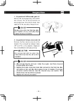
Page 94: ...ation and greasing of lift truck parts 1 Clean the grease nipples with a clean cloth and apply grease to the following points with a grease gun Grease Used Albania EP2 Mast trunnion and Tilt rod end At one location each on right and left Inspecting the fan belt tension while the engine is running is dangerous Always stop the engine before inspecting the rotating sections and peripheral areas WARNI...

Page 95: ... Brake brake inching pedal linkage pin e Hydraulic control lever linkage Apply grease until it overflows and then wipe off the excess CAUTION Wipe off old grease with a clean cloth If oil or grease gets on the operator s seat handles or steps wipe it off immediately Failure to do so could cause the operator to slip and fall CAUTION a c b d e ...

Page 96: ...guard and back rest trouble Inspect the above items and following parts monthly 3 Lubricate the following places with machine oil using an oiler g Parking brake h Accelerator pedal linkage Wipe off any oil that leaks out after lubricating Use clean oil and grease The containers must be also clean and prevent dusts and the like from getting into the containers CAUTION g h h LPG Electronic controlle...
Page 97: ...ient and replace if dirty Replace the oil for the first time after six months of use and after that replace it every 12 months ADVICE Dipstick for transmission Do not permit dirt to enter the transmission when the oil level is checked CAUTION When inspecting the oil level rotate the engine and then stop and inspect within one minute Replace the torque converter return filter element for the first ...

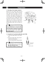
Page 98: ...ement Take care to the assembly position top and bottom of cover 4 Inspection of spark plug Gasoline and LPG 1 Check the high tension cord connec tion 2 Remove the plug with a plug wrench Check the burning state Check the gap between the electrodes Use compressed air to clean the filter element Air pressure must be less than 210 kPa 2 1 kgf cm2 Apply the air from the inside to the outside of the f...

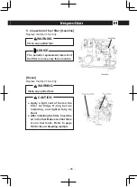
Page 99: ...c replacement interval of the filter is once every three months ADVICE Gasoline Fuel filter WARNING Clean any spilled fuel CAUTION Apply a light coat of fuel on the filter cartridge O ring before installing and tighten fully by hand After installing the filter bleed the air in the fuel Make sure that there are no fuel leaks Refer to page 100 for the air bleeding method ...

Page 100: ...he tar 5 After stopping the drip of tar turn off the drain cock Electronic controlled Engine 4 Remove the drain bolt on the bottom of the LPG regulator to drain the tar 5 After stopping the drip of tar install the drain bolt by applying sealant 7 Draining of sedimenter Diesel Always bleed the air in the sedimenter after draining Refer to page 99 Check the LPG leakage after draining the tar Clean a...

Page 101: ...COMPACT 71 to 85 N m 729 to 875 kgf m 2 0 to 3 5 ton 117 to 212 N m 1800 to 2160 kgf m 11 Inspection of counter weight retention bolt Check for loose bolt and damage on the counter weight and its installation Bolt tightening torque 1 5 to 2 0 ton COMPACT 597 to 717 N m 6100 to 7300 kgf m 2 0 to 3 5 ton 1187 to 1424 N m 12100 to 14500 kgf m Wipe off any oil that leaks out after lubricating Use clea...

Page 102: ...ot permit the hot oil to touch the skin and cause a burn WARNING Drain the oil while it is still warm approx 30 to 40 C To avoid dirt from mixing in wash the lift truck and make sure that the lubrication greasing sections and oil level gauge are clean Refer to the table of Recommended Oils and Grease for the engine oil and use according to the temperature Inspect and replace the oil in a place tha...

Page 103: ...n the wing nut to open the drain valve on the bottom of the fuel filter Drain some fuel and any water into a container until clean fuel flows from the filter 2 Turn the wing nut to close the drain valve Apply engine oil on the base O ring when installing Install the filter and then tighten by 2 3 of a turn after the O ring has contacted the filter body Refer to the instructions on page 111 for the...

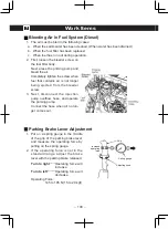
Page 104: ...g ejected from the bleeder screw 3 Next disconnect the injection pump overflow hose and operate the priming pump Connect the hose when air no lon ger comes out Parking Brake Lever Adjustment 1 Put on a spring gauge in the middle of the grip of the parking brake lever and measure the operating force by pulling on the spring gauge 2 If the operating force is not in the standard range adjust the brak...

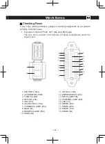
Page 105: ...s located in the left side of engine compartment under the engine hood 1 BATTERY 100A 2 ALTERNATOR 100A 3 FUSE PULLER 4 OPT IGN 20A 5 IGN 10A 6 GAUGE V ECU 10A 7 TURN BACK LAMP 20A 8 MAIN 5A 9 HEAD TAIL LAMP 25A 10 HORN 5A 11 OPT ECU 20A 12 WIPER HEATER 20A 13 STOP LAMP 10A 14 WORKING LAMP 20A 15 LPG 5A 16 SPARE 25A 17 SPARE 20A 18 SPARE 10A 19 SPARE 5A 3 8 1 2 9 10 11 12 13 14 15 16 4 17 5 18 6 1...

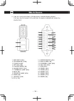
Page 106: ...LTERNATOR 100A 3 FUSE PULLER 4 OPT IGN 20A 5 FUEL OTHERS 10A 6 GAUGE V ECU 10A 7 TURN BACK LAMP 20A 8 MAIN 5A 9 HEAD TAIL LAMP 25A 10 HORN 5A 11 OPT ECU 20A 12 ETC 15A 13 WIPER HEATER 20A 14 STOP LAMP 10A 15 WORKING LAMP 20A 16 IGN COIL 30A 17 ECM 30A 18 SPARE 30A 19 SPARE 25A 20 SPARE 10A 21 SPARE 20A 22 SPARE 15A 23 SPARE 5A 3 8 1 2 9 10 11 12 13 14 15 16 17 18 4 19 5 20 21 6 22 23 7 ...

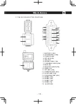
Page 107: ...E PULLER 4 OPT IGN 20A 5 IGN 10A 6 GAUGE V ECU 10A 7 TURN BACK LAMP 20A 8 MAIN 5A 9 HEAD TAIL LAMP 25A 10 HORN 5A 11 OPT ECU 20A 12 WIPER HEATER 20A 13 STOP LAMP 10A 14 WORKING LAMP 20A 15 SPARE 25A 16 SPARE 20A 17 SPARE 10A 18 SPARE 5A 19 GLOW 60A 8 3 15 16 17 18 4 5 7 6 1 2 19 9 10 11 12 13 14 ...

Page 108: ... negative jumper cable to the negative terminal b Always connect the jumper cable that is the ground cable last c Always connect the jumper cables to the discharged battery before connecting them to the booster battery How to Use Coupler Pin The coupler pin at the back of the counter weight is to be used when the truck tire is caught in the gutter or mud The coupler pin can be used when loading th...

Page 109: ...el and hard surface Put on parking brake 3 Put stoppers on the tire diagonal to the one that is to be changed 2 Setting the jack 1 Changing front wheel tire Set the jack underneath the mast Or lift the upper part of the mast or use a hydraulic equipment 2 Changing rear tire Set the jack underneath the counterweight Or lift the counterweight ...

Page 110: ...ir from the tires before the tires are removed from the lift truck WARNING Never lift the truck with the overhead guard If it is necessary to lift the truck consult with your authorized service dealer CAUTION The jack to be used should have larger capacity than the designated capacity Jack up piece should be right on the jack piece underneath the counter weight Confirm that the mast trunnion insta...

Page 111: ...venly in contact Do not get under the truck while jacking up If the jack comes off it is very dangerous WARNING Confirm that the wheel assembly bolts is not loose before loosening the hub nuts Do not loosen the wheel assembly bolts Loosen only hub nuts CAUTION Before Jacking up remove load off the truck and be sure to used stoppers on tire When jacking up no one should be at the operator seat Afte...

Page 112: ...kgf cm Spacer and Outer 294 to 343 N m 3000 to 3500 kgf cm Rear wheel 157 to 188 N m 3000 to 3500 kgf cm 1 5 2 0 ton COMPACT Front tire 196 to 216 N m 2000 to 2200 kgf cm Rear tire 98 to 123 N m 1000 to 1250 kgf cm Check all wheel nuts after 2 to 5 hours of operation when new lift trucks begin operation and on all lift trucks when the drive wheels have been removed and installed Tighten the nuts i...

Page 113: ...bly of tire tube rim and the like and to pump air into tire The lift truck tires use high pressure and is very dangerous Pumping air requires the certificate of completion of special training Pumping air into tires off the truck should be started after inspecting tire rim bolts and nuts Put tire in a fence while pumping air for safety Never pump air beyond the standard air pressure When pumping ai...

Page 114: ...he nuts that fasten the rim halves together are toward the brake drum when they are installed CAUTION Wash lift truck When washing a lift truck protect the electric components from being splashed with water Wash a lift truck with care to prevent the electric components among others controller section tilt angle sensor section shift switch section horn button section turn signal switch section dash...

Page 115: ...Oil Water X Check for Leaks See NOTE 6 Hydraulic Hoses X Check Condition See Parts Manual Coolant Hoses X Check Condition See Parts Manual Fuel Tank Gas CIL 1 2 ton COMPACT 52 liter 2 3 5 ton 69 liter 86 Octane Gasoline Minimum Fuel Tank LPG CIL 29 9 liter 7 9 gal 15kg LPG HD 5 Fuel Tank Diesel CIL 1 2 ton COMPACT 52 liter 2 3 5 ton 69 liter Diesel oil No 2 Indicator Icons Horn Fuses and Relays X ...

Page 116: ...n 397 to 485 N m Wheel Nuts Steer Wheels X Check Torque 1 2 ton COMPACT 98 to 123 N m 2 3 5 ton 157 to 188 N m Battery and Cable Terminals X Clean Accelerator Cable C 1 Cable See Parts Manual Engine Oil GCT Engines X CIL C 3 8 liter w filter See NOTE 3 20 to 30 C SAE 10W 30 5 to 40 C SAE 30 API SE and above Engine Oil Yanmar Engines X CIL C 8 8 liter w filter See NOTE 3 20 to 30 C SAE 10W 30 5 to ...

Page 117: ...ectors GCT Engine EGI X 4 Injectors Check and Replace If Required Spark Plugs GCT Engines X Check Plug Wires 4 Plugs See Parts Manual 0 8 0 9 mm Cooling System X CIL C 7 5 liter K21 4TNE92 7 8 liter K25 4TNE98 50 Water and 50 Ethylene Glycol Boron Free Antifreeze Clean Debris From Radiator Core X See NOTE 5 Transmission Oil X C 8 3 liter DEXRON II or III Transmission Oil Filter C 1 Filter See NOTE...

Page 118: ...OTE 9 Multipurpose Grease See NOTE 1 Service Brakes X Check Lining Thickness 1 0 mm Minimum Differential and Drive Axle Oil X C 1 2 ton COMPACT 5 0 liter 2 3 5 ton 6 5 liter SAE 80W 90 or 85W 140 NOTE 1 Multipurpose grease with 2 to 4 Molybdenum Disulfide NOTE 2 Heavy duty or high temperature operations require more frequent checks NOTE 3 Change Oil and filters on NEW lift trucks at first 200 hour...

Page 119: ... 1 Cup dust seal etc of brake master cylinder and wheel cylinder 1 2 Brake hoses and or tubes 1 2 3 Brake reservoir hose 2 4 4 Power steering hoses 2 5 Service brake switch hydraulic type 2 6 Fuel supply and or return hoses 2 4 7 Rubber parts in the power steering system 2 8 Lift chains 2 4 ...

Page 120: ...Main Specification Table 9 116 Vechicle body dimensions A L M C D J F N G K I E H B ...

Page 121: ... top of forks mm E 3200 3240 3275 Overall width Tire frame mm F 1070 1070 1135 1070 1135 1070 Hight Height of canopy guard mm G 2060 2060 2060 Height with collapsed mast mm H 1995 1995 1995 Height with extended mast mm 4105 4105 4105 Fork length mm I 920 920 920 Fork spread max min mm J 915 205 915 205 910 250 Wheelbase mm K 1410 1410 1410 Tread Standard tread front rear mm L M 915 905 950 930 950...

Page 122: ...h Tire frame mm F 1160 1140 1160 1140 1160 1140 Hight Height of canopy guard mm G 2130 2130 2130 Height with collapsed mast mm H 1995 1995 1995 Height with extended mast mm 4120 4120 4120 Fork length mm I 920 920 1070 Fork spread max min mm J 1010 250 1010 250 1010 250 Wheelbase mm K 1625 1625 1625 Tread Standard tread front rear mm L M 970 1000 970 1000 970 1000 Ground clearance Mast mm N 120 120...

Page 123: ...rall width Tire frame mm F 1160 1140 1235 1140 1235 1140 Hight Height of canopy guard mm G 2130 2150 2150 Height with collapsed mast mm H 1995 2060 2140 Height with extended mast mm 4120 4125 4125 Fork length mm I 1070 1070 1070 Fork spread max min mm J 1010 250 1060 250 1065 305 Wheelbase mm K 1625 1700 1700 Tread Standard tread front rear mm L M 970 1000 1010 1000 1010 1000 Ground clearance Mast...

Page 124: ...070 1070 1135 1070 1135 1070 Hight Height of canopy guard mm G 2060 2060 2060 Height with collapsed mast mm H 1995 1995 1995 Height with extended mast mm 4105 4105 4105 Fork length mm I 920 920 920 Fork spread max min mm J 915 205 915 205 910 250 Wheelbase mm K 1410 1410 1410 Tread Standard tread front rear mm L M 915 905 950 930 950 930 Ground clearance Mast mm N 110 110 110 Unladen weight Standa...

Page 125: ...40 1160 1140 1160 1140 Hight Height of canopy guard mm G 2130 2130 2130 Height with collapsed mast mm H 1995 1995 1995 Height with extended mast mm 4120 4120 4120 Fork length mm I 920 920 1070 Fork spread max min mm J 1010 250 1010 250 1010 250 Wheelbase mm K 1625 1625 1625 Tread Standard tread front rear mm L M 970 1000 970 1000 970 1000 Ground clearance Mast mm N 120 120 120 Unladen weight Stand...

Page 126: ...235 1140 1235 1140 Hight Height of canopy guard mm G 2130 2150 2150 Height with collapsed mast mm H 1995 2060 2140 Height with extended mast mm 4120 4125 4125 Fork length mm I 1070 1070 1070 Fork spread max min mm J 1010 250 1060 250 1065 305 Wheelbase mm K 1625 1700 1700 Tread Standard tread front rear mm L M 970 1000 1010 1000 1010 1000 Ground clearance Mast mm N 120 140 140 Unladen weight Stand...

Page 127: ...NG MANUAL H1 5 3 5XT 07 15 OPERATING MANUAL Manual de Instrucciones H1 5 1 8XT H2 0XTS H2 0 3 5XT D475 D466 4136698 DO NOT REMOVE THIS MANUAL FROM THIS UNIT NO QUITE ESTE MANUAL DE ESTA UNIDAD Printed in Japan SK0715 ...

Reviews: