12
CAUTION
Use only Hyster approved brushes to protect
commutator and to obtain maximum brush life.
1
2
3
4
SHUNT
LENGTH
SHUNT
LENGTH
5
6
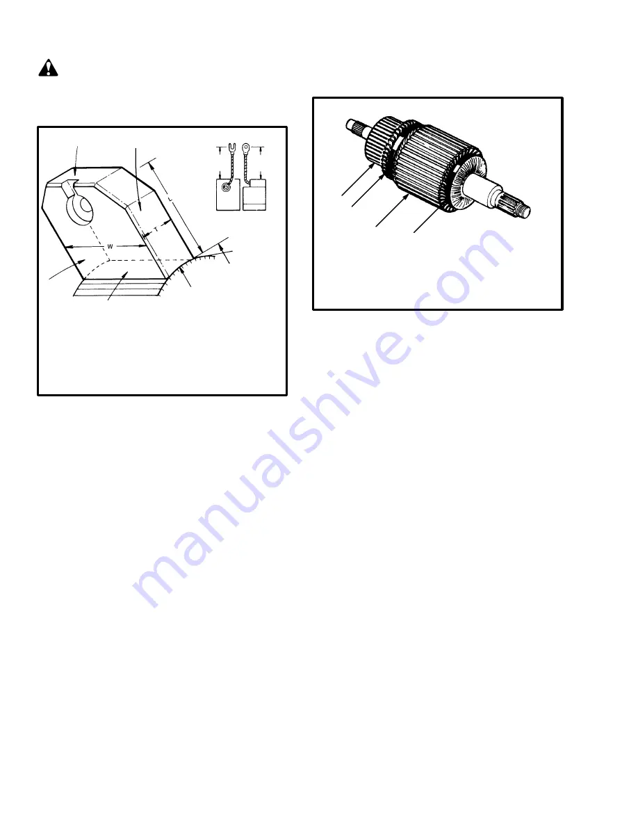
FIGURE 15. BRUSH DESIGN DETAIL
1. COMMUTATOR END
2. FRONT SIDE
3. TOP
4. RIGHT SIDE
5. BEVEL
6. CONCAVE FACE
6936
ARMATURE
The armature assembly consists of several laminations
of iron located around a steel shaft, the copper armature
windings and a commutator. Each commutator segment
is separated by heat resistant, nonconducting material,
and is attached to an armature coil. Circular bands hold
the armature coils in place. Between each copper
armature band is a laminated iron core. These reinforce
the magnetic field for each coil field. The armature is
wired so current from one brush makes contact with a
commutator bar, energizes an armature coil and returns
through another commutator bar and brush. As the
armature assembly turns, alternate commutator
segments are energized changing the polarity of the
armature coils in rotating sequence (May vary among
motor manufacturers.)
1
2
3
4
FIGURE 16. ARMATURE ASSEMBLY
1. LAMINATED IRON CORES
2. COMMUTATOR
3. ARMATURE COILS
4. BAND
6937
COMMUTATOR
Description
The commutator is formed of alternate copper segments
(bars) and mica plates. The mica plates physically
separate and electrically insulate the bars. The mica
plates are undercut below the commutator surface to
prevent interference with the sliding action of the
brushes on the surface of the commutator. The bars are
wedge shaped and form a cylinder when assembled.
Each bar has a riser at one end to make armature coil
connections. The bars are held in position by the
clamping action of a wedge ring with lock nut (or
manufactured integral). Mica cones, contoured to fit
between the shell and wedge ring insulate the bars from
ground (armature). The commutator provides sliding
electrical contact between the brushes and the moving
armature coils. It acts as a reversing switch to allow the
current to flow through the coils in the proper direction
at all times.


