background image

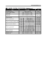
SERVICING INFORMATION  9-30

NOTE

Fuel type

Fuel tank capacity

Engine oil & Transmission oil type

Engine oil capacity

Transmission oil capacity

API Over SL (SAE 10W/40)

Gasoline used should be graded 91 octane or higher.

An unleaded gasoline is recommened.

800 

900 

1,000 

400 

410 

ITEM

SPECIFICATION

FUEL + OIL

Change

Oil Filter change

Overhaul

Change

Overhaul

TIRE PRESSURE

COLD INFLATION

TIRE PRESSURE

NORMAL RIDING

FRONT

SOLO RIDING

kPa

kgf/

㎠ ㎠

psi

kPa

kgf/

㎠ ㎠

psi

172

197

1.75

2.00

25.0

29.0

172

246

1.75

2.50

25.0

36.0

DUAL RIDING

REAR

Summary of Contents for MS3 125

Page 1: ...and service This manual will help you know the vehicle better so that you can assure your customers of your optimum and quick service WARNING This manual is intended for those who have enough knowledge and skills for servicing HYOSUNG vehicles Without such knowledge and skills you should not attempt servicing by relying on this manual only Instead please contact your nearby authorized HYOSUNG moto...

Page 2: ...e sections is listed on the previous page as GROUP INDEX select the section where you are looking for 3 Holding the manual as shown at the right will allow you to find the first page of the section easily 4 On the first page of each section its contents are listed Find the item and page you need COMPONENT PARTS Example Front wheel ...

Page 3: ...d Measure in voltage range Measure in resistance range Measure in current range Use special tool Use engine coolant Torque control required Data beside it indicates specified torque Apply oil Use engine oil unless otherwise specified Apply SUPER GREASE A Apply SILICONE GREASE Apply MOLY PASTE Apply BOND 1215 Use fork oil DEFINITION SYMBOL DEFINITION SYMBOL Apply SUPER GREASE C Measure in continuit...

Page 4: ... Pump I IAP Sensor Intake Air Pressure Sensor IAPS IAT Sensor Intake Air Temperature Sensor IATS IG Ignition ISC Solenoid Idle Speed Control Solenoid L LCD Liquid Crystal Display LED Light Emitting Diode LH Left Hand M Max Maximum Min Minimum O O2 Sensor Oxygen Sensor O2S R RH Right Hand S SAE Society of Automotive Engineers SAV Solenoid Secondary Air Valve Solenoid T TDC Top Dead Center TO Sensor...

Page 5: ...er GY Green with Yellow tracer GrB Gray with Black tracer GrR Gray with Red tracer GrW Gray with White tracer OB Orange with Black tracer OL Orange with Blue tracer OG Orange with Green tracer OR Orange with Red tracer OW Orange with White tracer OY Orange with Yellow tracer RB Red with Black tracer RW Red with White tracer WB White with Black tracer WL White with Blue tracer WR White with Red tra...

Page 6: ...NOTE Difference between photographs and actual motorcycles depends on the markets ...

Page 7: ...FORMATION INFORMATION LABELS 1 1 GENERAL PRECAUTIONS 1 2 SERIAL NUMBER LOCATION 1 3 FUEL OIL AND ENGINE COOLANT RECOMMENDATIONS 1 4 BREAK IN PROCEDURES 1 6 EXTERIOR ILLUSTRATION 1 7 SPECIFICATIONS 1 8 CONTENTS 1 ...

Page 8: ...particular service operation ask a more experienced mechanic for advice WARNING CAUTION NOTE Please read this manual and follow its instructions carefully To emphasize special information the symbol and the words WARNING CAUTION and NOTE have special mean ings Pay special attention to the messages highlighted by these signal words CAUTION Indicates a potential hazard that could result in vehicle d...

Page 9: ...n removing the battery disconnect the battery lead wire first and then the battery lead wire When reconnecting the battery connect the battery lead wire first and then the battery lead wire Finally cover the battery terminal with the terminal cover When performing service to electrical parts if the service procedures do not require use of battery power diconnect the battery lead wire at the batter...

Page 10: ...ehicle Identification Number is stamped on the right downside frame The engine serial number is stamped on the left rearside of the crankcase assembly These numbers are required especially for registering the machine and ordering spare parts FRAME SERIAL NUMBER ENGINE SERIAL NUMBER ...

Page 11: ...mage the transmission When refilling the oil don t allow the dust to get inside Wipe the spilled oil up immediately Don t put the patch on the filler cap It could disturb the oil to be provided and damage the transmission WARNING Since the brake system of this vehicle is filled with a glycol based brake fluid by the manufacturer do not use or mix different types of fluid such as silicone based and...

Page 12: ...e atmospheric temperature in your area does not go down to freezing point Hyosung recommends the use of HYOSUNG COOLANT anti freeze engine coolant If this is not available use an equivalent which is compatible with an aluminum radiator LIQUID AMOUNT OF WATER ENGINE COOLANT For engine coolant mixture information refer to cooling system section page 6 1 CAUTION Mixture of anti freeze engine coolant ...

Page 13: ...st possible materials are used and all machined parts are finished to a very high standard but it is still necessary to allow the moving parts to BREAK IN before subjecting the engine to maximum stresses The future performance and reliability of the engine depends on the care and restraint exercised during its early life The general rules are as follows Keep to these break in procedures Interval M...

Page 14: ...ATION EXTERIOR ILLUSTRATION 765 WIDTH 750 120 1 365 HEIGHT 640 740 735 300 455 2 125 LENGTH Position lamp Rear reflector Tail Brake lamp Turn signal lamp Rear Turn signal lamp Front Head lamp 1 500 WHEEL BASE 425 775 875 ...

Page 15: ...cooled 1 cylinder 73 0 mm 2 87 in 59 6 mm 2 35 in 249 5 15 2 in3 Fuel injection Electric starter Wet sump 57 0 mm 2 24 in 48 8 mm 1 92 in 124 5 7 6 in3 Type Number of cylinder Bore Stroke Piston displacement Fuel system Starter system Lubrication system Dry shoe automatic centrifugal type 7 31 0 900 2 333 V belt drive 10 82 0 804 2 414 Clutch Reduction ratio Transmission Drive belt SPECIFICATIONS ...

Page 16: ... lamp 15 A HI 12V 55 W 1 LO 12V 55 W 1 Position 12V 5 W 2 LED type 12V 21 5 W 1 12V 5 W 1 10 B T D C at2 000rpmand28 B T D C at4 000rpm Ignition type Ignition timing Spark plug Battery Turn signal lamp Brake Tail lamp License plate lamp LED Light Emitting Diode Fuel tank Engine oil oil replace with oil filter replace overhaul Transmission oil oil replace overhaul Coolant Front fork oil capacity On...

Page 17: ...RANCE 2 7 SPARK PLUG 2 10 FUEL HOSE 2 11 THROTTLE CABLE PLAY 2 11 ENGINE IDLE SPEED 2 11 ENGINE OIL AND OIL FILTER 2 12 TRANSMISSION OIL 2 14 ENGINE COOLANT 2 15 RADIATOR HOSE 2 17 BRAKE SYSTEM 2 18 STEERING 2 22 FRONT FORK 2 22 REAR SHOCK ABSORBER 2 22 TIRE 2 23 CHASSIS BOLTS AND NUTS 2 23 COMPRESSION PRESSURE 2 24 AUTOMATIC CLUTCH INSPECTION 2 25 CONTENTS 2 PERIODIC MAINTENANCE ...

Page 18: ...r shock absorber Chassis bolts and nuts General lubrication Inspect Inspect Inspect Inspect Inspect Tighten Lubricate Inspect Inspect Inspect Inspect Inspect Inspect Inspect Tighten Lubricate Replace every 4 years Replace every 2 years CHASSIS 2 18 2 18 2 18 2 23 2 22 2 22 2 22 2 23 2 4 PERIODIC MAINTENANCE SCHEDULE The chart below lists the recommended intervals for all the required periodic serv...

Page 19: ...move the two bolts of the rear carrier Push the side cover for the rear side Disconnect the tail lamp coupler Lift the front end of the side cover and prop it up as shown side Insert the crank end of the side cover stay into the hole of the side cover CAUTION Proceed with care Do not damage the cover reflector and lamp Handle plastic and paint finished parts with care to avoid scratching or damage...

Page 20: ... inner cover to inspect the fuel injection system easily USE OF HELMETBOX INNER COVER Position the motorcycle on the center stand Raise the seat Lift the helmetbox inner cover knob carefully CAUTION Proceed with care Do not damage the personal trunk and helmetbox inner cover Handle plastic parts with care to avoid damage ...

Page 21: ... stand pivot and spring hook Side stand pivot and spring hook Speedometer gear box Throttle grip Front brake lever holder Throttle cable O Motor oil G Grease NOTE Before lubricating each part clean off any rusty spots and wipe off any grease oil dirt or grime Lubricate exposed parts which are subject to rust with either motor oil or grease whenever the motorcy cle has been operated under wet or ra...

Page 22: ... stay Refer to page 2 2 Unscrew and remove the eight screws Remove the air cleaner case cover Take off the air cleaner element Fill a washing pan of a proper size with a non flammable cleaning solvent Immerse the air cleaner element in the cleaning solvent and wash it Gently squeeze the air cleaner element between the palms of both hands to remove the excess sol vent do not twist or wring the elem...

Page 23: ...ner element for tears A torn element must be replaced If driving under dusty conditions clean the air cleaner element more frequently The surest way to accelerate engine wear is to operate the engine without the element or with torn ele ment Make sure that the air cleaner element is in good condition at all times Life of the engine depends largely on this component Inspect Interval Tighten Initial...

Page 24: ...t valve clearances at the distances indicated above and adjust the valve clearances to specification if necessary Lift and support the side cover with the side cover stay Refer to page 2 2 VALVE CLEARANCE Remove the spark plug Disconnect the breather hose Inspect Interval Inspect Initial 1 000 km and Every 4 000 km there after 2 7 PERIODIC MAINTENANCE ...

Page 25: ...ted 1 at the time of periodic inspection 2 when the valve mechanism is serviced and 3 when the camshafts are removed for servicing Remove the crankcase cleaner case Remove the valve timing inspection plug NOTE The piston must be at top dead center TDC on the compression stroke in order to check or adjust the valve clearance The valve clearance should only be checked when the engine is cold ...

Page 26: ...der head Select the tappet that agree with tappet clearance vertical line and shim NO horizontal line as refer to the tappet shim selection chart Refer to page 9 37 38 Adjust valve timing install the camshaft housing and the tension adjuster After the crankshaft rotate about 10 times measure the valve clearance If the clearance be not correct adjust the standard clearance as the same manner above ...

Page 27: ... type Standard type Cold type SPARK PLUG SPECIFICATION TYPE Inspect Interval Clean Initial 1 000 km and Every 4 000 km thereafter Replace Every 8 000 km SPARK PLUG GAP Measure the spark plug gap using a thickness gauge If the spark plug gap is out of specification adjust the gap ELECTRODE Check to see the worn or burnt condition of the elec trodes If it is extremly worn or burnt replace the spark ...

Page 28: ...lows Position the motorcycle on the center stand Withdraw the protection Loosen the lock nut of the throttle cable Turn the adjuster in or out to obtain the correct play ENGINE IDLE SPEED CAUTION To avoid damaging the cylinder head threads first finger tighten the spark plug and then tight en it to the specified torque using the spark plug wrench Inspect Interval Inspect Initial 1 000 km and Every...

Page 29: ...cycle upright with the center stand Place an oil drain pan below the engine Remove the engine oil level gauge Drain the engine oil by removing the engine oil drain plug located on the left downside of the engine The oil should be changed while the engine is warm Oil filter replacement at the above intervals should be done together with the engine oil change Inspect Interval Replace Initial 1 000 k...

Page 30: ...new engine oil through the oil filler hole When performing an oil change with oil filter replacement the engine will hold about 900 of oil Use an engine oil that meets the API service classifications of over SL and that has a viscosity rating of SAE 10W 40 CAUTION When reassembling the oil filter make sure that the oil filter is installed If the filter is installed improperly serious engine damage...

Page 31: ... with adequate capacity Fit and tighten the transmission oil drain bolt to the specified torque TRANSMISSION OIL Install the transmission oil filler cap Check the transmission oil level using the trans mission oil level bolt hole and top up as required without exceeding the transmission oil level bolt hole Tighten the transmission oil level bolt to the specified torque Operate the engine a few min...

Page 32: ...ntil the level reaches the F FULL level line Inspect Interval Replace Every 2 years WARNING You can be injured by scalding fluid or steam if you open the radiator cap when engine is hot After the engine cools wrap a thick cloth around cap and carefully remove the cap by turning it a quarter to allow pressure to escape and then turn the cap all the way off OPEN THE RADIATOR CAP Remove the radiator ...

Page 33: ...gine coolant through the radiator cap inlet up to the inlet neck Bleed the air from the engine coolant circuit as fol lowing procedure NOTE For engine coolant information refer to page 6 1 WARNING Do not open the radiator cap when the engine is hot as you may be injured by escaping hot liquid or vapor Engine coolant may be harmful if swallowed or if it comes in contact with the skin or eyes If eng...

Page 34: ...hermostat Start up the engine and bleed air from the radiator cap inlet and the connector bolt of the thermostat completely Add engine coolant up to the radiator cap inlet Repeat the above procedure until no air bleed from the radiator cap inlet Close the radiator cap securely After warming up and cooling down the engine several times add the engine coolant up to the F FULL level line of the reser...

Page 35: ... of brake pad wear can be checked by observing the grooved limit on the pad When the wear exceeds the grooved limit replace the pads with new ones CAUTION Replace the brake pad as a set otherwise braking performance will be adversely affected WARNING The brake system of these motorcycles are filled with a glycol based brake fluid Do not use or mix different types of fluid such as silicone based or...

Page 36: ...otorcycle on a level surface and keep the handlebars straight Remove the master cylinder reservoir cap and diaphragm Suck up the old brake fluid as much as possible Fill the reservoir with new brake fluid Connect a transparent hose to the air bleeder valve and insert the other end of the hose into a receptacle Front brake caliper mounting bolt 18 28 N m 1 8 2 8 kgf m Rear brake caliper mounting bo...

Page 37: ...king performance of the brake caliper The presence of air is indicated by sponginess of the brake lever and also by lack of braking force Considering the danger to which such trapped air exposes the machine and rider it is essential that after remounting the brake and restoring the brake system to the normal condition the brake fluid circuit be purged of air in the following manner Fill the master...

Page 38: ...r grip Then close the air bleeder valve pump and squeeze the brake lever and open the valve Repeat this process until the fluid flowing into the receptacle no longer contains air bubbles Close the air bleeder valve and disconnect the hose Fill the reservoir with brake fluid to the upper line Bleed the rear brake s air with the same manner of front brake NOTE While bleeding the brake system repleni...

Page 39: ...ull forward If play is found perform steering stem nut adjustment as described in page 8 31 of this manual STEERING Inspect the front forks for oil leakage scoring or scratches on the outer surface of the inner tubes Replace any defective parts if necessary FRONT FORK Inspect the rear shock absorber for oil leakage and mounting rubbers including engine mounting for wear and damage Replace any defe...

Page 40: ...ened to their specified torque Refer to page 9 17 COLD INFLATION TIRE PRESSURE Front Rear SOLO RIDING kPa 172 197 1 75 2 00 25 0 29 0 172 246 1 75 2 50 25 0 36 0 kgf cm2 psi DUAL RIDING kPa kgf cm2 psi TIRE PRESSURE If the tire pressure is too high or too low steering will be adversely affected and tire wear increased Therefore maintain the correct tire pressure for good enter key roadability or s...

Page 41: ...EDURE COMPRESSION PRESSURE The compression of a cylinder is a good indicator of its internal condition The decision to overhaul the cylinder is often based on the results of a compression test Periodic mainte nance records kept at your dealership should include compression reading for each maintenance service Standard Service limit 15 kgf cm2 at 500 rpm 13 kgf cm2 at 500 rpm Compression pressure N...

Page 42: ...he side cover stay Refer to page 2 2 Connect the engine tachometer to the high ten sion cord Seated on the motorcycle with the motorcycle on level ground increase the engine RPMs slowly and note the RPM at which the motorcycle begins to move forward CLUTCH LOCK UP INSPECTION Perform this inspection to determine if the clutch is engaging fully and not slipping Apply the front and rear brakes as fir...

Page 43: ...CLUTCH 3 36 ENGINE REASSEMBLY 3 37 CONTENTS CAUTION Mark an identification of assembly location on each removed part so that each will be restored to the original position during reassembly Wash clean and dry the removed parts before inspecting and measuring Oil the rotating or sliding parts before assembly Make sure to use the correct type of lubricant where specified Check that each rotating or ...

Page 44: ...NTING ENGINE REMOVAL Remove the Seat side cover rear fender assembly Refer to page 8 7 Drain the engine oil Refer to page 2 12 Remove the engine oil filter Refer to page 2 13 Drain the engine coolant Refer to page 2 16 Drain the transmission oil Refer to page 2 14 Disconnect the battery lead wire Disconnect the breather hose ...

Page 45: ...nition coil lead wires Loosen the air cleaner hose clamp screw Remove the air cleaner mounting bolts Remove the air cleaner box Disconnect the starter motor lead wire and the engine ground lead wire Disconnect the magneto coupler ...

Page 46: ...3 3 ENGINE Remove the exhaust pipe nuts Remove the water hoses and Remove the muffler mounting bolts ...

Page 47: ...ngine mounting bolt and nut Remove the engine from the frame ENGINE REMOUNTING Remount the engine in the reverse order of engine removal Support the chassis with the center stand Support the engine assembly with a proper engine jack Tighten the engine mounting bolt and rear shock absorber mounting bolt right and left to the specified torque Engine mounting bolt 40 50 N m 4 0 5 0 kgf m Rear shock a...

Page 48: ...mount of engine oil Refer to page 2 12 3 5 ENGINE Adjust the following items to the specification Throttle cable play Refer to page 2 11 Idling inspect Refer to page 2 11 Check for leakage of the engine oil transmission oil and engine coolant ENGINE DISASSEMBLY Remove the insulator and O ring Remove the intake pipe bolts and then remove the intake pipe together with the throttle body CAUTION Put t...

Page 49: ...r and the oil return tank Remove the clutch cover Remove the gasket and dowel pins Loosen the fixed drive face nut and clutch housing nut Remove fixed drive face and clutch housing Remove the movable drive face assembly with the spacer ...

Page 50: ... Remove the belt roller only for Remove the thermostat case Remove the four water pump case mounting bolts and then remove the water pump case Remove the magneto cover 3 7 ENGINE ...

Page 51: ...er idle gear shaft and the starter idle gear Remove the magneto rotor by using the special tool Loosen the magneto rotor nut Remove the key and starter clutch gear Rotor remover sliding shaft 09930 30102 Rotor remover 09930 30162 ...

Page 52: ...mounting bolt and then remove the oil pump cover 3 9 ENGINE Remove the oil pump chain guide and oil pump Remove the oil pump sprocket circlip oil pump chain and oil pump sprocket Remove the crank balancer driven gear nut Only for ...

Page 53: ...e the three front rear fender mounting bolts and then remove the front rear fender Remove the rear suspension arm Remove the rear axle nut Remove the cam chain tension adjuster Remove the cam chain tension adjuster bolt ...

Page 54: ...es and then remove the cylinder head cover Remove the cam chain guide and camshaft housing Remove the dowel pins intake camshaft and exhaust camshaft Remove the three cylinder head base nuts NOTE Do not drop the dowel pins and camshaft drive chain into the crankcase ...

Page 55: ...onal stages NOTE If the cylinder does not come off easily lightly tap it using a plastic hammer Remove the cam chain guide Remove the cylinder head Remove the two cylinder base nuts and then remove the cylinder Remove the cylinder head gasket and dowel pins ...

Page 56: ...e piston pin circlip Draw out the piston pin and remove the piston Remove the crank balancer drive gear Remove the crank balancer driven No 2 gear and the crank balancer driven No 1 gear Only for Hold the crankshaft immovable using the special tool Conrod holder 09910 20115 Loosen the crank balancer drive nut using the special tool Crank balancer socket wrench 09940HP7600 ...

Page 57: ...r and then remove the rear wheel Remove the rear axle shaft together with the gear box cover Remove the circlip Remove the rear axle shaft and final driven gear from the gear box cover Remove the idle shaft idle driven gear and drive shaft ...

Page 58: ... halves using the special tool Remove the crankshaft from the crankcase Crankcase separator 09920 13120 NOTE The crankcase separator plate is parallel with the end face of the crankcase CAUTION The crankshaft must remain in the left crankcase half Remove the crank balancer Only for ...

Page 59: ...N AND SERVICE CYLINDER HEAD DISASSEMBLY Remove the tappets and shims by hand or by using a magnet CAUTION Identify the position of each removed part Organize the parts in their respective group for example exhaust or intake so that they can be installed in their original positions Compress the valve springs and then remove the valve cotters from the valve stem using the special tools ...

Page 60: ... MOLY PASTE to each oil seal and press fit them into position Apply MOLY PASTE to the valve as shown and then insert them into the valve guides Install the valve spring with the smaller pitch facing the cylinder head CAUTION Do not reuse the oil seals CAUTION When inserting each valve into the valve guides make sure not to damage the lip of the oil seal MOLY PASTE MOLY PASTE 3 17 ENGINE Head direc...

Page 61: ... 0 05 mm 0 002 in CYLINDER HEAD DISTORTION Decarbonize in combustion chamber Check the gasket surface of the cylinder head for dis tortion using a straightedge and thickness gauge Take clearance reading at several places as indicat ed If any clearance reading exceeds the service limit replace the cylinder head with a new one Thickness gauge 09900 20806 VALVE FACE WEAR Visually inspect each valve f...

Page 62: ...When cold TAPPET SHIM WEAR When measuring the valve clearance the clearance should be within the standard range Exhaust valve Intake valve Inspect the tappet for wear and scratch If modification or scratch is present replace the tappet When you checked the valve clearance if the valve clearance is wide please replace the present shim into thick one if the valve clearance is nar row please replace ...

Page 63: ...ve about 10 mm 0 39 in from the valve seat Measure the valve stem deflection in two direc tions X and Y perpendicular to each other Position the dial gauge as shown If the deflection exceeds the service limit determine whether the valve or the guide should be replaced with a new one EX IN Dial gauge 09900 20606 Magnetic stand 09900 20701 Valve stem diameter Standard IN EX VALVE STEM DIAMETER Measu...

Page 64: ...free length and also by the force required to compress them If the spring length is less than the service limit or if the force required to compress the valve spring is not within specification replace the valve spring Vernier calipers 09900 20101 Valve spring freelength IN EX Service limit Valve spring tension IN EX Standard 40 67 mm 1 601 in 18 50 21 50 kgf 40 79 47 40 lbs at length 31 8 mm 1 25...

Page 65: ...WEAR Worn down cams are often the cause of mistimed valve operation resulting in reduced output power The limit of cam wear is specified for both intake and exhaust cams in terms of cam height which is to be measured with a micrometer Replace camshafts if found it worn down to the limit Micrometer 25 50 mm 09900 20202 Camshaft journal oil clearance IN EX Service limit 0 15 mm 0 006 in CAMSHAFT JOU...

Page 66: ...959 21 980 mm 0 8645 0 8654 in Standard Camshaft runout IN EX Service limit 0 10 mm 0 004 in If the camshaft journal oil clearance exceeds the ser vice limit measure the inside diameter of the camshaft housing and outside diameter of the camshaft journal Replace the camshaft or the cylin der head and camshaft housing depending upon which one exceeds the specification CAMSHAFT RUNOUT Support the va...

Page 67: ...R Check that the push rod slides smoothly with the lock shaft handle counter clockwise If it does not slide smoothly replace the cam chain tension adjuster with a new one CAM CHAIN TENSIONER Check the contacting surface of the cam chain ten sioner If it is worn or damaged replace it with a new one Cylinder gauge set 09900 20508 Standard Service limit CAM CHAIN AND CAM CHAIN GUIDE Check the cam cha...

Page 68: ...between the cylinder bore and out side diameter of the piston PISTON PIN HOLE BORE Using a dial calipers measure the piston pin hole bore both the vertical and horizontal directions If the measurement exceeds the service limit replace the piston with a new one 15 mm 0 6 in Piston to cylinder clearance Standard Service limit 0 050 0 060 mm 0 0020 0 0024 in 19 030 mm 0 7492 in 15 030 mm 0 5917 in 0 ...

Page 69: ...er at three position both the ends and the center If any of the measurements is founds less than the service limit replace the pin with a new one Micrometer 0 25 mm 09900 20201 Vernier calipers 09900 20101 Piston pin diameter Service limit 1st 2nd Piston ring free end gap Service limit PISTON RING END GAP INSPECTION Assembly condition Insert the piston ring squarely into the cylinder using the pis...

Page 70: ...fted up measure the clearance on the bottom side of the ring using a thickness gauge If any clearance reading exceeds the service limt replace both the piston and piston rings Standard Standard Piston ring thickness Standard Piston ring groove width Oil 2nd 1st 2 01 2 03 mm 0 079 0 080 in 1 01 1 03 mm 0 040 0 041 in 1 01 1 03 mm 0 040 0 041 in 2nd 1st 0 970 0 990 mm 0 0382 0 0390 in 0 970 0 990 mm...

Page 71: ...e limit Conrod small end I D 15 006 15 014 mm 0 5908 0 5911 in 15 040 mm 0 5921 in Conrod small end I D Dial calipers 09900 20605 CONROD DEFLECTION INSPECTION Wear on the big end of the conrod can be estimated by checking the movement of the small end of the rod Turn the conrod and see if it moves smoothly without play and noise This method can also be used to check the extent of wear on the parts...

Page 72: ...etc with new ones Standard 0 10 0 45 mm 0 004 0 018 in 1 0 mm 0 040 in Service limit Conrod big end side clearance CRANKSHAFT CRANKSHAFT RUNOUT INSPECTION With the right and left crank journals supported using a V block turn the crankshaft slowly At this time measure the crankshaft end runout using a dial gauge If the runout exceeds the service limit replace the crankshaft with a new one Crankshaf...

Page 73: ...D BALANCER DRIVEN GEAR Only for DISASSEMBLY Disassemble the crank balancer and balancer driven gear as shown in the illustration REASSEMBLY Reassemble the crank balancer and balancer driven gear in the reverse order of disassembly ...

Page 74: ...cts are found or measurement exceeds the limit replace the rollers as a set Vernier calipers 09900 20101 MOVABLE DRIVE FACE INSPECTION Inspect the belt contacting surface of movable drive face for scratches or discoloration caused by buring If any defects are found replace the movable drive face with a new one CAUTION The drive belt contact surfaces of the movable drive face should be cleaned to b...

Page 75: ...river Clutch shoe nut Clutch shoe assembly Spring Remove the three pins and movable driven face from the fixed driven face WARNING Gradually back off the clutch shoe assembly pressed down by hand to reduce the clutch spring load Releasing the hand suddenly may cause the parts to fly apart CAUTION Do not attempt to disassemble the clutch shoe assembly ...

Page 76: ...tion caused by burning Measure the clutch housing inside diameter with an inside calipers If any defects are found or measurememt exceeds the limit replace the clutch housing with a new one Service limit Clutch housing I D 134 5 mm 5 295 in MOVABLE DRIVEN FACE SPRING INSPECTION Measure the free length of movable driven face spring If length is shorter than the service limit replace the spring with...

Page 77: ...nstall the movable driven face to the fixed driven face Vernier caliper 09900 20101 CAUTION Always keep the drive belt away from any greasy matter If drive belt is contaminated with grease or oil clean it with neutral detergent CAUTION When installing the movable driven face insert it while using a 0 1 mm thickness gauge as a guide to prevent the damage of the oil seal lip Install the three pins a...

Page 78: ...hoe nut to the specified torque with the special tool Refer to page 3 51 installation of the movable driven face and clutch Clutch shoe nut 50 N m 5 0 kgf m Rotor holder 09930 40113 Install the spring and clutch shoe assembly Install the clutch shoe nut while pressing down the clutch shoe assembly Install the movable driven face seat ...

Page 79: ...ation is smooth Also check that the gear is locked when attempted to turn in the other direction If a large resistance is felt or noise occurs when turning the gear check the starter clutch gear slid ing surface for wear or damage If any abnormal condition is found replace the starter clutch with a new one OIL SEAL INSPECTION Damage to the lip of the oil seal may result in leak age of the fuel air...

Page 80: ...ine the width between the webs referring to the figure when rebuilding the crankshaft Install the jet NOTE Apply engine oil to each running and sliding part before reassembling the engine Always keep the drive belt drive faces and driven faces away from any greasy matter Width between webs Standard 51 0 0 1 mm 2 008 0 004 in 51 0 0 1 mm 2 008 0 004 in ...

Page 81: ...aces with a cleaning solvent Fit the dowel pins into the left crankcase Apply BOND 1215 to the right crankcase BOND 1215 CAUTION Coat the sealant evenly without break Application of sealant must be performed with in a short period of time Take extreme care not to let sealant enter into the oil hole or bearing Assemble the crankcases with in few minutes Tighten the crankcase bolts diagonally and ev...

Page 82: ... COVER Install the dowel pins and the gasket Install the gear box cover together with the rear axle shaft IDLE SHAFT Install the idle shaft idle driven gear and drive shaft REAR WHEEL Install the rear wheel and then install the rear axle spacer Gear box cover bolt 18 N m 1 8 kgf m CAUTION Apply engine oil to each gear and shaft ...

Page 83: ...haft with the recess of the crank balancer drive gear Only for Hold the crankshaft immovable using the special tool CAUTION Make sure that the punch mark on the balancer drive gear is aligned with the punch mark on the balancer driven No 1 gear Only for Conrod holder 09910 20115 Using the special tool tighten the balancer drive gear nut to the specified torque Crank balancer socket wrench 09940HP7...

Page 84: ...roove and then install the two side rails The spacer and side rails do not have a designated top and bottom They can be installed in any position CAUTION When installing the spacer be careful not to allow its two ends to overlap in the groove Position the piston ring gaps as shown Before inserting the piston into its cylinder check that the gaps are properly positioned 2nd ring and lower side rail...

Page 85: ...rs Hold each piston ring with the piston ring sections positioned correctly and put it into the cylinder Make sure that the piston rings are caught by the cylinder skirt MOLY PASTE NOTE Install the piston with the punch mark on the piston head facing toward the exhaust side NOTE When mounting the cylinder after attaching the cam chain keep the cam chain taut The cam chain must not be caught betwee...

Page 86: ...der secure it by tightening the bolts in diagonal stages Tighten the cylinder head bolts diagonally to the specified torque Cylinder base nut 7 11 N m 0 7 1 1 kgf m CAUTION Use a new cylinder head gasket to prevent gas leakage NOTE Apply engine oil to the threaded parts of the cylinder head bolts and its washers Be sure to install the washer with rounded side facing up Cylinder head bolt 40 45 N m...

Page 87: ...r hold the camshaft steady and lightly pull up the cam chain to remove any slack between the cam chain sprocket and exhaust camshaft sprocket The exhaust camshaft sprocket has an arrow marked 1 Turn the exhaust camshaft so that the arrow is aligned with the gasket surface of the cylinder head Engage the cam chain with the exhaust camshaft sprocket The other arrow marked 2 should now be pointing st...

Page 88: ...3 45 ENGINE NOTE The cam chain should now be on all three sprockets Be careful not to move the crankshaft until the camshaft housing and cam chain tensioner are secured 16 Pins 1 2 3 ...

Page 89: ...d caps of the cylin der head cover gasket as shown Apply engine oil to both sides of the washer Lightly tighten the cylinder head cover bolts in diagonal stages and then tighten them to the specified torque NOTE NOTE When tightening the camshaft housing bolts the piston position must be at TDC on the compres sion stroke BOND 1215 CAUTION Use a new washers Camshaft housing bolt 8 12 N m 0 8 1 2 kgf...

Page 90: ...e cylinder Tighten the cam chain tension adjuster mounting bolts to the specified torque Tighten the cam chain tension adjuster bolt to the specified torque REAR SUSPENSION ARM Install the rear axle nut Install the rear suspension arm Cam chain tension adjuster mounting bolt 8 12 N m 0 8 1 2 kgf m Cam chain tension adjuster bolt 8 12 N m 0 8 1 2 kgf m Rear axle nut 100 140 N m 10 0 14 0 kgf m ...

Page 91: ...nut to the specified torque Only for OIL PUMP Install the oil pump and oil pump chain guide Tighten the oil pump mounting bolts to the speci fied torque Install the oil pump sprocket Install the oil pump sprocket circlip Engage the oil pump chain With the other side of the oil pump chain engaged with the crankshaft gear Conrod holder 09910 20115 Crank balancer driven gear nut Only for 40 60 N m 4 ...

Page 92: ...otor nut Tighten the magneto rotor nut to the specified torque STARTER CLUTCH GEAR Install the starter clutch gear and the key IDLE GEAR Install the starter idle gear shaft and the starter idle gear Oil pump cover mounting bolt 8 12 N m 0 8 1 2 kgf m Magneto rotor nut 40 60 N m 4 0 6 0 kgf m NOTE Make sure to engage the starter clutch with the starter clutch gear ...

Page 93: ...t 8 12 N m 0 8 1 2 kgf m CAUTION Replace the O ring with new one MAGNETO COVER Install the dowel pins and gasket CAUTION Replace the gasket with a new one Water pump case mounting bolt 8 12 N m 0 8 1 2 kgf m THERMOSTAT CASE Install the thermostat case Tighten the thermostat case mounting bolts to the specified torque BELT ROLLER Only for Install the belt roller Tighten the belt roller bolt to the ...

Page 94: ...ct surface pulley face CAUTION Pull the center area of upper and lower belt lines to be close to each other to prevent the belt from expanding Tighten the clutch housing nut to the specified torque MOVABLE DRIVE FACE ASSEMBLY Check that no roller inside the movable drive face is out of position from the slot Install the movable drive face assembly CAUTION Degrease the inner surface of the clutch h...

Page 95: ...TER MOTOR Install the starter motor and the oil return tank To obtain proper contact of the drive V belt turn the fixed drive face until the fixed drive face and the movable driven face can rotate synchronously CAUTION Check that the fixed drive face is not fouled with grease or other substance and if found clean and degrease completely Check that the parts are properly engaged with the spline Fix...

Page 96: ...3 ENGINE THROTTLE BODY Install the insulator and O ring Install the intake pipe together with the throttle body Tighten the intake pipe bolts to the specified torque Intake pipe bolt 8 12 N m 0 8 1 2 kgf m ...

Page 97: ...TION 4 17 C15 WT SENSOR CIRCUIT MALFUNCTION 4 20 C17 IAP SENSOR CIRCUIT MALFUNCTION 4 22 C21 IAT SENSOR CIRCUIT MALFUNCTION 4 24 C22 OXYGEN SENSOR CIRCUIT MALFUNCTION 4 26 C23 TO SENSOR CIRCUIT MALFUNCTION 4 27 C24 IGNITION COIL MALFUNCTION 4 27 C27 ISC SOLENOID RANGE ABNORMAL 4 28 C32 FUEL INJECTOR CIRCUIT MALFUNCTION 4 29 C37 SAV SOLENOID MALFUNCTION 4 31 C41 FUEL PUMP RELAY CIRCUIT MALFUNCTION ...

Page 98: ...be sure to hold the coupler body and do not pull the lead wires Inspect each terminal on the connector coupler for looseness or bending Inspect each terminal for corrosion and contamination The terminals must be clean and free of any foreign material which could impede proper terminal contact Inspect each lead wire circuit for poor connection by shaking it by hand lightly If any abnormal condition...

Page 99: ...tor for bend and female connector for excessive opening Also check the coupler for locking looseness corrosion dust etc FUSE When a fuse blows always investigate the cause to correct it and then replace the fuse Do not use a fuse of a different capacity Do not use wire or any other substitute for the fuse ECU VARIOUS SENSORS Since each component is a high precision part great care should be taken ...

Page 100: ...the components of the FI system instantly when reverse power is applied Removing any battery terminal of a running engine is strictly prohibited The moment such removal is made damaging counter electromotive force will be applied to the ECU which may result in serious damage Before measuring voltage at each terminal check to make sure that battery voltage is 11V or higher Terminal voltage check at...

Page 101: ...wise accurate measurements may not be obtained and personal injury may result USING TESTERS Use well charged batteries in the tester Be sure to set the tester to the correct testing range USING THE TESTER Incorrectly connecting the and probes may cause the inside of the tester to burnout If the voltage and current are not known make measurements using the highest range Check that no voltage is app...

Page 102: ...ening angle and various compensations These compensations are determined according to the signals from various sensors that detect the engine and driving conditions Intake Air Pressure Sensor IAP Sensor Intake air pressure signal Basic fuel injection time Compensation Ultimate fuel injection time Pick up coil Throttle Position Sensor TP Sensor Various Sensors Injectors Engine speed signal Throttle...

Page 103: ...it monitors the voltage signal for compensation of the fuel injection time volume A longer injection time is needed to adjust injection volume in the case of low voltage At high speed the injection time volume is increased When starting engine additional fuel is injected during cranking engine During acceleration the fuel injection time volume is increased in accordance with the throttle opening s...

Page 104: ...4 7 FI SYSTEM DIAGNOSIS FI SYSTEM PARTS LOCATION Speedometer TP sensor IAT sensor ISC solenoid Fuel injector Ignition coil Fuel pump relay ECU 3 4 2 6 7 5 1 ...

Page 105: ...FI SYSTEM DIAGNOSIS 4 8 IAP sensor WT sensor TO sensor SAV solenoid Pick up coil Oxygen sensor ECU 10 12 11 8 9 10 ...

Page 106: ...ck the special tool is necessary to read the code of the malfunction items USER MODE The FI check lamp comes on for about three seconds whenever the ignition switch is set to ON position with the engine stopped as a test of the injection system operation The check lamp must go off after three seconds If the check lamp comes on during normal engine operation it means that the fuel injection system ...

Page 107: ... devices are indicated in the code form CAUTION Do not disconnect the ECU lead wire couplers before checking the malfunction code or the malfunction code memory is erased and the malfunction code can not be checked Confirm the malfunction code after turn the ignition switch ON position or cranking the engine for few seconds MALFUNCTION NO YES C code is indicated from small numeral to large one FI ...

Page 108: ...2 C37 C41 C43 Throttle position sensor TPS Water temperature sensor WTS Intake air pressure sensor IAPS Intake air temperature sensor IATS Oxygen sensor O2S Tip over sensor TOS IG coil Idle speed control solenoid ISC solenoid Fuel injector Secondary air valve solenoid SAV solenoid Fuel pump relay Oxygen sensor heater O2S heater MALFUNCTION PART REMARKS ...

Page 109: ... problem Mileage FI Check lamp Malfunction display code LCD Always ON Sometimes ON Always OFF Good condition No code Malfunction code PROBLEM SYMPTOMS Difficult Starting Poor Driveability No cranking Hesitation on acceleration No initial combustion Back fire After fire No combustion Lack of power Poor starting at Surging cold warm always Abnormal knocking Other Engine rpm jumps briefly Other Poor ...

Page 110: ... F C Always Always Sometimes times day month Only once Under certain condition Urban Suburb Highway Mountainous Uphill Downhill Tarmacadam Gravel Other Cold Warming up phase Warmed up Always Other at starting Immediately after start Racing without load Engine speed rpm During driving Constant speed Accelerating Decelerating Right hand corner Left hand corner At stop Motorcycle speed when problem o...

Page 111: ...se it Be sure to read PRECAUTIONS for Electrical Circuit Service Refer to page 4 1 before inspection and observe what is written there Lift and support the side cover with the side cover stay Refer to page 2 2 Connect the special tool to the dealer mode coupler at the wiring harness and the ignition switch is set to ON position Turn the special tool s switch ON position and check the malfunction c...

Page 112: ...C17 is indicated The sensor voltage should be the following 0 1 V sensor voltage 4 6 V Without the above range for 4 sec and more C15 is indicated The sensor should produce following voltage 0 1 V sensor voltage 4 8 V Without the above range for 4 sec and more C14 is indicated The sensor voltage should be the following for more than 2 sec after ignition switch turns ON position 4 5 V sensor voltag...

Page 113: ... is indicated Injector wiring coupler connection power supply to the injector When the IC of the ECU electric current gets 6A and more C24 is indicated When the secondary air valve solenoid voltage is not input in ECU C37 is indicated Secondary air valve solenoid lead wire coupler connection Fuel pump relay connecting lead wire power source to fuel pump relay fuel injector No voltage is applied to...

Page 114: ...n 5 Measure the voltage at the OB wire and ground 6 If OK then measure the voltage at the OB wire and BW wire DETECTED CONDITION POSSIBLE CAUSE Output voltage is out of the specified range 0 1 V Sensor voltage 4 8 V TP sensor circuit open or short TP sensor malfunction ECU malfunction YES NO Go to Step 2 Loose or poor contacts on the ECU coupler Open or short circuit in the OB wire or BW wire TP s...

Page 115: ...and ground 5 If OK then measure the TP sensor resistance between and 6 Turn the throttle grip and measure the resistance TP sensor continuity Ϊ Infinity Ground TP sensor resistance Throttle valve is closed Throttle valve is opened Approx 4 75 Approx 1 81 YES NO Go to Step 3 Reset the TP sensor position correctly Replace the TP sensor with a new one Are the resistance and continuity OK Tester knob ...

Page 116: ...tle grip Is the voltage OK YES NO OB LY or BW wire open or shorted to ground or poor or connection If wire and connection are OK intermittent trouble or faulty ECU Recheck each terminal and wire harness for open circuit and poor connection If check result is not satisfactory replace TP sensor with a new one TP sensor output voltage Throttle valve is closed Throttle valve is opened Tester knob indi...

Page 117: ... Measure the voltage between G wire terminal and ground 5 If OK then measure the voltage between G wire terminal and BW wire terminal DETECTED CONDITION POSSIBLE CAUSE Output voltage is out of the specified range 0 1 V Sensor voltage 4 6 V WT sensor circuit open or short WT sensor malfunction ECU malfunction YES NO Go to Step 2 Loose or poor contacts on the ECU coupler Open or short circuit in the...

Page 118: ...ox 5 790 Approx 2 450 Approx 1 148 Approx 0 586 Approx 0 322 0 32 20 68 40 104 60 140 80 176 Is the voltage OK YES NO G or BW wire open or shorted to ground or poor or connection If wire and connection are OK intermittent trouble or faulty ECU Recheck each terminal and wire harness for open circuit and poor connection Replace the WT sensor with a new one Tester knob indication Resistance ECU Coupl...

Page 119: ...DETECTED CONDITION IAP sensor voltage is out of the specified range 0 1 V Sensor voltage 4 8 V NOTE Note that atmospheric pressure varies depending on weather conditions as well as altitude Take that into consideration when inspecting voltage Clogged vacuum passage between throttle body and IAP sensor Air being drawn from vacuum passage between throttle body and IAP sensor IAP sensor circuit open ...

Page 120: ... Insert the needle pointed probes to the lead wire coupler 3 Start the engine at idle speed 4 Measure the IAP sensor output voltage at the wire side coupler between BL and BW wires IAP sensor output voltage Approx 4 0 4 2 V when ignition switch ON BL BW Is the voltage OK YES NO OB BL or BW wire open or shorted to ground or poor or connection If wire and connection are OK intermittent trouble or fa...

Page 121: ...rn the ignition switch ON position 5 Measure the voltage between Lg wire terminal and ground 6 If OK then measure the voltage between Lg wire terminal and BW wire terminal DETECTED CONDITION POSSIBLE CAUSE Output voltage is out of the specified range 0 1 V Sensor voltage 4 6 V IAT sensor circuit open or short IAT sensor malfunction ECU malfunction YES NO Go to Step 2 Loose or poor contacts on the ...

Page 122: ...rouble or faulty ECU Recheck each terminal and wire harness for open circuit and poor connection Replace the IAT sensor with a new one NOTE IAT sensor resistance measurement method is the same way as that of the WT sensor Refer to page 6 8 for details ECU Coupler Resistance Intake Air Temp IAT sensor resistance Approx 53 30 Approx 31 52 Approx 12 33 Approx 5 19 Approx 2 42 10 14 0 32 20 68 40 104 ...

Page 123: ... heater malfunction ECU malfunction POSSIBLE CAUSE INSPECTION 1 Remove the right side front lower cover 2 Turn the ignition switch OFF position 3 Check the Oxygen sensor coupler for loose or poor contacts Is OK NO YES BR or BW wire open or shorted to ground or poor or connection If wire and connection are OK intermittent trouble or faulty ECU Recheck each terminal and wire harness for open circuit...

Page 124: ...d poor connection Replace the TO sensor with a new one Is OK C23 TO SENSOR CIRCUIT MALFUNCTION INSPECTION 1 Lift and support the side cover with the side cover stay Refer to page 2 2 2 Turn the ignition switch OFF position 3 Check the TO sensor coupler for loose or poor contacts 4 Remove the TO sensor DETECTED CONDITION POSSIBLE CAUSE Output voltage is out of the specified range 4 5 V Sensor volta...

Page 125: ... POSSIBLE CAUSE ISC solenoid s step is out of the specified range O step solenoid step 100 step ISC solenoid ISC solenoid s step is out of the specifie range ECU malfunction Is OK NO YES Replace the ISC solenoid with a new one Gr GR Y or W wire loose or poor contacts on the ISC solenoid coupler or poor 34 32 33 or 25 connection If wire and connection are OK intermittent trouble or faulty ECU Reche...

Page 126: ...nnect the injector couplers and measure the resistance between terminals 5 If OK then check the continuity between injector terminals and ground DETECTED CONDITION POSSIBLE CAUSE Fuel injector not comes in voltage from battery Injector circuit open or short Injector malfunction ECU malfunction Injector resistance 11 5 13 5 Ϊ at 20 68 Injector continuity Ϊ Infinity Ground Is the resistance OK YES N...

Page 127: ...can be detected only 3 seconds after ignition switch is turned ON position YES NO YG wire open or shorted to ground or poor connection If wire and connection are OK intermittent trouble or faulty ECU Recheck each terminal and wire harness for open circuit and poor connection Inspect the fuel pump or fuel pump relay Refer to page 5 4 Is the voltage OK Tester knob indication Voltage ECU Coupler ...

Page 128: ...SPECTION 1 Lift and support the side cover with the side cover stay Refer to page 2 2 2 Turn the ignition switch OFF position 3 Check the SAV solenoid coupler for loose or poor contacts 4 Connect the SAV solenoid coupler 5 Turn the ignition switch ON position 6 Measure the voltage at the wire side coupler between GL wire and ground C37 SAV SOLENOID MALFUNCTION DETECTED CONDITION POSSIBLE CAUSE SAV...

Page 129: ... voltage is applied to the both injectors for 3 sec after the contact of fuel pump relay is turned ON position Or voltage is applied to the both injectors when the contact of fuel pump is OFF position Fuel pump relay circuit open or short Fuel pump relay malfunction ECU malfunction YES NO GW wire open or shorted to ground or poor connection If wire and connection are OK intermittent trouble or fau...

Page 130: ...ON 1 Remove the right side front lower cover 2 Turn the ignition switch OFF position 3 Check the Oxygen sensor heater coupler for loose or poor contacts If OK then measure the Oxygen sensor heater voltage 4 Disconnect the coupler and then the ignition switch ON position 5 Measure the voltage between OB wire terminal and B or ground wire terminal DETECTED CONDITION POSSIBLE CAUSE Oxygen sensor heat...

Page 131: ...upport the side cover with the side cover stay Refer to page 2 2 Remove the IAP sensor from the intake pipe Install the IAP sensor in the reverse order of removal TP SENSOR INSPECTION The throttle position TP sensor is installed at the left side of the throttle body Refer to page 4 17 TP SENSOR REMOVAL AND INSTALLATION WT SENSOR INSPECTION The water temperature WT sensor is installed at the rear s...

Page 132: ... side cover stay Refer to page 2 2 Remove the IAT sensor from the air cleaner case Install the IAT sensor in the reverse order of removal TO SENSOR INSPECTION REMOVAL AND INSTALLATION The tip over TO sensor is located in the side front cover Refer to page 4 27 Lift and support the side cover with the side cover stay Refer to page 2 2 Remove the TO sensor from the side front cover Install the TO se...

Page 133: ...MESH FILTER INSPECTION AND CLEANING 5 5 FUEL LEVEL GAUGE INSPECTION 5 5 THROTTLE BODY 5 6 REMOVAL 5 7 DISASSEMBLY 5 8 CLEANING 5 10 INSPECTION 5 10 REASSEMBLY 5 11 INSTALLATION 5 12 THROTTLE CABLE ADJUSTMENT 5 12 FUEL INJECTOR REMOVAL 5 12 FUEL INJECTOR INSPECTION 5 12 FUEL INJECTOR INSTALLATION 5 12 CONTENTS 5 FUEL SYSTEM AND THROTTLE BODY ...

Page 134: ...5 1 FUEL SYSTEM AND THROTTLE BODY FUEL SYSTEM ...

Page 135: ...ove the Seat side cover rear fender assembly Refer to page 8 7 Disconnect the fuel level gauge coupler Remove the fuel tank guide Remove the fuel tank mounting bolts Remove the fuel pump coupler Remove the fuel injector hose return hose and breather hose CAUTION After disconnecting the fuel injector hose insert a blind plug into the end to stop fuel leakage ...

Page 136: ... pump assembly mounting bolts lightly in diagonal stages and then tighten them in the above tightening order CAUTION As gasoline leakage may occur in this operation keep away from fire and sparks WARNING Gasoline is highly flammable and explosive Keep heat spark and flame away Tighten the fuel tank mounting bolts to the specified torque Tighten the fuel tank guide bolts NOTE Apply a small quantity...

Page 137: ...3 363 kPa 48 4 52 6 psi WARNING Before removing the special tool turn the ignition switch to OFF position and release the fuel pressure slowly Gasoline is highly flammable and explosive Keep heat sparks and flame away If the fuel pressure is lower than the specification inspect the following items Fuel hose leakage Clogged fuel filter Pressure regulator Fuel pump If the fuel pressure is higher tha...

Page 138: ...ne FUEL LEVEL GAUGE INSPECTION Measure resistance between the terminals when float is at the position instead below If the resistance measured is out of the specification replace the gauge with a new one Fuel level meter inspection Refer to page 7 14 Fuel float position Resistance between terminals F 1 2 E Approx 4 10 Ϊ Approx 35 45 Ϊ Approx 95 105 Ϊ First check the insulation between and terminal...

Page 139: ...FUEL SYSTEM AND THROTTLE BODY 5 6 THROTTLE BODY ...

Page 140: ...dy Loosen the clamp screw Disconnect the throttle cable Disconnect the fuel injector hose and breather hose Loosen the intake pipe bolt Remove the throttle body assembly Remove the insulator and O ring CAUTION After disconnecting the throttle cable do not snap the throttle valve from full open to full close If may cause damage to the throttle valve and throttle body ...

Page 141: ... pipe and O ring from the intake pipe and throttle body DISASSEMBLY Remove the ISC solenoid Remove the IAP sensor Remove the fuel injector CAUTION The throttle body is assembled precisely in factory Do not disassemble it other than shown in this manual ...

Page 142: ...5 9 FUEL SYSTEM AND THROTTLE BODY CAUTION Never remove the throttle valve CAUTION Never remove the TP sensor CAUTION Never remove the idle screw CAUTION Never remove the throttle lever stopper screw ...

Page 143: ...ct the IAP sensor Refer to page 4 22 Inspect the TP sensor Refer to page 4 17 WARNING Some throttle body cleaning chemicals especially dip type soaking solutions are very corrosive and must be handled carefully Always follow the chemical manufacture s instructions on proper use handling and storage CAUTION Do not use wire to clean passageways Wire can damage passageways If the components cannot be...

Page 144: ...ne oil to the new O ring Install the fuel injector by pushing them straight to throttle body Tighten the fuel injector bolt to the specified torque CAUTION Never operate the idle screw and throttle lever stopper screw to avoid variations of the carburetion setting CAUTION Replace the O ring with a new ones CAUTION Replace the O ring with the new one Never turn the injector while pushing it Fuel in...

Page 145: ...EL INJECTOR INSPECTION The fuel injector can be checked without removing it from the throttle body Inspect the fuel injector Refer to page 4 29 FUEL INJECTOR INSTALLATION Install the fuel injector Refer to page 5 11 FUEL INJECTOR REMOVAL Lift and support the side cover with the side cover stay Refer to page 2 2 Disconnect the injector coupler Remove the fuel injector hose Refer to page 5 7 Remove ...

Page 146: ...ENGINE COOLANT 6 1 COOLING CIRCUIT 6 2 RADIATOR 6 2 COOLING FAN 6 5 COOLING FAN THERMO SWITCH 6 6 WATER TEMPERATURE SENSOR 6 8 THERMOSTAT 6 9 WATER PUMP 6 11 COOLING SYSTEM 6 CONTENTS ...

Page 147: ...Refer to Right figure Do not use a radiator anti leak additive 50 Engine coolant including reserve tank capacity Anti freeze Water 0 575 ℓ 0 575 ℓ WARNING You can be injured by scalding fluid or steam if you open the radiator cap when the engine is hot After the engine cools wrap a thick cloth around cap and carefully remove the cap by turning it a quarter turn to allow pressure to escape and then...

Page 148: ...fer to page 8 3 6 Drain engine coolant by removing the drain bolt Disconnect the cooling fan thermo switch lead wire coupler Disconnect the radiator outlet hose and radiator cap hose WATER PUMP THERMOSTAT BY PASS BREATHER WT SENSOR COOLING FAN THERMO SWITCH RADIATOR RESERVOIR TANK CYLINDER CYLINDER HEAD ...

Page 149: ...t or trash stuck to the fins must be removed Use of compressed air is recommended for this cleaning Remove the radiator by the mounting bolts Disconnect reserve tank hose Disconnect the cooling fan motor lead wire cou pler Remove the radiator inlet hose ...

Page 150: ...lant Install the reservoir tank in the reverse order of removal Fill the reservoir tank to the upper level line Pour engine coolant Refer to page 2 16 Bleed air from the cooling circuit Refer to page 2 17 Fins bent down or dented can be repaired by straightening them with the blade of a small screw driver INSPECTION OF WATER HOSE Remove the lower leg rear shield Refer to page 8 7 Any water hose fo...

Page 151: ...adiator Route the radiator hoses properly Pour engine coolant Refer to page 2 16 Bleed air from the cooling circuit Refer to page 2 17 Install the front leg shield and leg shield cover INSTALLATION Install the cooling fan to the radiator COOLING FAN INSPECTION Remove the front leg shield and leg shield cover Refer to page 8 3 6 Disconnect the cooling fan motor lead wire cou pler and its thermo swi...

Page 152: ...ler Remove the cooling fan thermo switch INSPECTION Check the thermo switch closing or opening tem peratures by testing it at the bench as shown in the figure Connect the thermo switch to a circuit tester and place it in the OIL contained in a pan which is placed on a stove Heat the oil to raise its temperature slowly and read the column thermometer when the switch closes of opens Cooling fan ther...

Page 153: ... front leg shield and leg shield cover INSTALLATION Install the cooling fan thermo switch in the reverse order of removal Pay attention to the following points Install a new O ring and apply engine coolant to the O ring Tighten the cooling fan thermo switch to the speci fied torque Cooling fan thermo switch 13 N m 1 3 kgf m ...

Page 154: ...CTION Check the engine coolant temperature by testing it at the bench as shown in the figure Connect the WT sensor to a circuit tester and place it in the WATER contained in a pan which is placed on a stove Heat the water to raise its temperature slowly and read the column thermometer and the ohmmeter If the resistance noted to show infinity or too much different resistance value replace the WT se...

Page 155: ...a string between flange as shown in the photograph Immerse the thermostat in the WATER contained in a beaker as shown in the illustration Note that the immersed thermostat is in suspen sion Heat the water by placing the beaker on a stove and observe the rising temperature on a ther mometer Read the thermometer just when opening the ther mostat This reading which is the temperature level at which t...

Page 156: ...of removal Pay attention to the following points Apply engine coolant to the rubber seal on the thermostat Install the thermostat Install the thermostat case cap Tighten the thermostat case cap bolts to the spec ified torque Pour engine coolant Refer to page 2 16 Bleed air from the cooling circuit Refer to page 2 17 Standard Over 8 0 mm at 90 Over 0 32 in at 194 Thermostat valve lift Thermostat ca...

Page 157: ...UMP REMOVAL AND DISASSEMBLY Drain engine coolant Refer to page 2 16 Disconnect the water hose Remove the water pump case Remove the magneto cover Remove the E ring from the impeller shaft Remove the O ring of the water pump case ...

Page 158: ...EARING Inspect the play of the bearing by hand while it is in the water pump case Rotate the inner race by hand to inspect abnormal noise and smooth rotation Replace the bearing if there is anything unusual BEARING CASE Visually inspect the bearing case for damage Replace the magneto cover if necessary Bearing remover 12mm 09921 20210 NOTE If there is no abnormal noise bearing removal is not neces...

Page 159: ...LY AND REMOUNTING Install the water pump in the reverse order of removal Pay attention to the following points Install the water pump case bearing Install the retainer oil seal magneto cover bearing and circlip Apply SUPER GREASE A to the impeller shaft Install the O ring and impeller to the water pump body ...

Page 160: ...ntil engine oil comes out from the hole of the bearing housing Apply engine collant to the O ring Install a new O ring Install the magneto cover Install the water pump case Connect the water hoses Pour engine coolant Refer to page 2 16 CAUTION Use a new O ring to prevent engine coolant leak age ...

Page 161: ...LOCATION OF ELECTRICAL COMPONENTS 7 1 IGNITION SYSTEM 7 3 CHARGING SYSTEM 7 5 STARTER SYSTEM 7 8 SWITCHES 7 11 LAMPS 7 12 BATTERY 7 15 CONTENTS ELECTRICAL SYSTEM 7 ...

Page 162: ...AL COMPONENTS Cooling fan motor Cooling fan thermo switch IAP sensor Fuel injector Ignition coil ISC solenoid TP sensor TO sensor Side stand switch Head lamp relay Coolingfanmotorrelay Fuel pump relay Turn signal relay Main relay Starter motor ...

Page 163: ...ELECTRICAL SYSTEM 7 2 Battery Main fuse 30A Head lamp fuse 15A ECU Starter motor relay Regulator Rectifier WT sensor SAV solenoid Oxygen sensor Oxygen sensor heater IAT sensor ...

Page 164: ...a new spark plug on the engine to ground it Measure the ignition coil primary peak voltage using the tester in the following procedure Connect the tester as follows Probe WL lead wire terminal Probe Ground NOTE Check that all the couplers are connected Check that the all battery is fully charged NOTE Do not disconnect the ignition coil plug cap lead wire couplers Pocket tester 09900 25002 IGNITION...

Page 165: ...If the resistance is not within the standard range replace the ignition coil with a new one WARNING While testing do not touch the tester probes and spark plug to prevent receiving an electric shock Tester knob indication Voltage 150 V and more Ignition coil primary peak voltage Tester knob indication Resistance ΪΪ Pocket tester 09900 25002 IGNITION COIL PLUG CAP RESISTANCE 3 5 5 5 Ϊ Terminal Term...

Page 166: ...e specified value check the magneto no load performance and regulator rectifier 7 5 ELECTRICAL SYSTEM CHARGING SYSTEM 13 5 15 0V at 5 000 rpm Standard charge CAUTION When making this test be sure that the battery is full charged condition Regulator Rectifier DCV Battery IG switch Pocket tester 09900 25002 A C generator IG switch Battery LOAD Regulator Rectifier Tester knob indication Voltage IC ...

Page 167: ...ester knob indication Resistance ΪΪ MAGNETO NO LOAD PERFORMANCE Disconnect the three lead wires from the magneto terminal Start the engine and keep it running at 5 000 rpm Using the pocket tester measure the AC voltage between the three lead wires If the voltage is under the specified value replace the magneto with a new one Over 70 V at 5 000 rpm Standard NO load per for mance of magneto Pocket t...

Page 168: ...ouplers Using the pocket tester measure the resistance between the terminals in the following table If the resistance checked is incorrect replace the regulator rectifier 3 4 3 4 1 2 1 2 3 4 3 4 1 2 1 2 3 4 3 4 1 2 1 2 1 2 1 2 1 2 32 1 2 1 2 1 2 32 Tester probe Tester probe Unit MΪ Pocket tester 09900 25002 Tester knob indication Resistance MΪΪ ...

Page 169: ...TER SYSTEM STARTER SYSTEM DESCRIPTION These motorcycles can only start the engine with squeezing the front or rear brake Brake switch Starter switch Ignition switch Engine stop switch Fuse Battery Starter relay Starter motor ECU ...

Page 170: ... the armature shaft If there is no continuity between the segments or there is continuity between the segment and shaft replace the starter motor with a new one Segment STARTER MOTOR INSPEC TION CARBON BRUSH Inspect the carbon brush for abnormal wear crack or smoothness in the brush holder If any damage are found replace the brush assembly with a new one Pocket tester 09900 25002 STARTER MOTOR REM...

Page 171: ...he O ring and remount the starter motor Tighten the stater motor mounting bolts to the specified torque STARTER MOTOR REASSEMBLY Reassemble the starter motor Pay attention to the following points Reassembly the starter motor as shown in the illustration SUPER GREASE A Starter motor mounting bolt 8 12 N m 0 8 1 2 kgf m ...

Page 172: ... replace the respective switch assemblies with new ones R O ON OFF IGNITION SWITCH O WB ON OFF FRONT REAR BRAKE LAMP SWITCH WB YR PUSH OFF STARTER SWITCH G O PUSH OFF HORN SWITCH YW Y W DIMMER SWITCH Sb L HAZARD WARNING SWITCH Pocket tester 09900 25002 Lg Sb B TURN SIGNAL SWITCH O OB ON OFF ENGINE STOP SWITCH ...

Page 173: ...tall the head lamp reverse the above sequence HEAD LAMP BEAM ADJUSTMENT Turn the adjuster screws of both head lamp bulbs with a screwdriver to adjust as follows turn CLOCKWISE to lower the beam Turn COUNTER CLOCKWISE to raise the beam CAUTION If you touch the bulb with your bare hands clean the bulb with a cloth moistened with alcohol or soapy water to prevent premature bulb failure Low beam Hi be...

Page 174: ...support the side cover with the side cover stay Refer to page 2 2 Turn the socket to the counter clockwise and pull it out at the lamp housing Push in the bulb turn it to the counter clockwise and pull it out To fit the replacement bulb push it in and turn it to the clockwise while pushing BRAKE TAIL LAMP CAUTION If you touch the bulb with your bare hands clean the bulb with a cloth moistened with...

Page 175: ...stration INSPECTION Using the pocket tester check the continuity between lead wires in the following illustration If the continuity measured incorrect replace the respective part CAUTION When making this test it is not necessary to remove the combination meter Pocket tester 09900 25002 Tester knob indication Continuity test ...

Page 176: ...When they were stained clothes will come into being a hole or painting will take off Consult a doctor When the battery electrolyte was dropped to the surface of land wash it with a vast quantity of water Neutralize by hydroxide bicarbonate of soda and so on FILLING ELECTROLYTE Put the battery on even land and remove the alu minum tape sealing Remove the cap at the electrolyte container Aluminum ta...

Page 177: ...that it does not fall Take precaution not to allow any fluid to spill Confirmation of pour Make sure that air bubbles are coming up each elec trolyte container and keep this position for more than about 20 minutes CAUTION The pouring of electrolyte may not be done if the electrolyte container is pushed slopely CAUTION If no air bubbles are coming up from a filler port tap the bottom two or three t...

Page 178: ...G OPERATION Using the pocket tester check the battery voltage If the voltage reading is less than the 12 0 V DC recharge the battery with a battery charger CAUTION Draw the empty receptacle out slowly because there may be a chance remaining electrolyte vaporize How to charge Standard Fast 0 8 A 5 10 hours 4 A 30 minutes After recharging wait for more than 30 minutes and check the battery voltage w...

Page 179: ...EXTERIOR PARTS 8 1 FRONT WHEEL 8 9 FRONT BRAKE 8 15 HANDLEBAR 8 23 FRONT FORK 8 25 STEERING 8 29 REAR WHEEL 8 32 REAR BRAKE 8 35 REAR SHOCK ABSORBER 8 37 CONTENTS CHASSIS 8 ...

Page 180: ...move the three screws of the leg shield front upper decoration Remove the leg shield front upper decoration Remove the screw of the right and left leg shield front decoration Remove the screw of the speedometer rear cover right and left Remove the right and left leg shield front decora tion ...

Page 181: ...rews of the windscreen Remove the windscreen Remove the two screws of the handle front cover Remove the handle front cover Remove the two screws of the handlebar Remove the handle rear cover center screw Remove the handle rear cover ...

Page 182: ... Remove the two screws of the speedometer front cover Remove the screw of the speedometer front cover right and left Remove the speedometer front cover FRONT LEG SHIELD Remove the handle cover Refer to page 8 1 Remove the speedometer cover Refer to above Remove the screws of the front fender to pre vent the front leg shield s damage Remove the front fender ...

Page 183: ...ct the head lamp coupler and position lamp coupler right and left Remove the front leg shield SPEEDOMETER Remove the handle cover Refer to page 8 1 Remove the speedometer cover Refer to page 8 3 Remove the front leg shield Refer to page 8 3 Remove the two screws Remove the two screws of the brace Disconnect the speedometer cable ...

Page 184: ...peedometer LEG SHIELD COVER Remove the front leg shield Refer to page 8 3 Remove the speedometer Refer to page 8 4 Remove the fuel tank cap radiator cap cover coolant reservoir tank filler cap cover coolant reservoir tank filler cap and ignition switch Remove the fuel tank hose clamp and breather hose clamp ...

Page 185: ...shield cover screws Remove the leg shield cover LOWER LEG FRONT SHIELD Remove the leg shield cover Refer to page 8 5 Remove the lower leg front shield screw Remove the lower leg front shield FUEL TANK LOWER COVER Remove the four screws of the fuel tank lower cover ...

Page 186: ...ion the motorcycle on the center stand Raise the seat Remove the two bolts in the personal trunk REAR LEG SHIELD Remove the rear leg shield bolts Remove the rear leg shield LOWER LEG REAR SHIELD Remove the screws of the right and left lower leg rear shield ...

Page 187: ... side cover rear fender assembly and push it for backward thor oughly Remove the Seat side cover rear fender assembly REAR MUD GUARD Remove the eight screws of the rear mud guard PASSENGER BACKREST To remove the passenger backrest Remove the four backrest cover mounting bolt Remove the backrest cover Remove the one backrest mounting bolt Remove the backrest Remove the two backrest bracket mounting...

Page 188: ...removing the mounting bolts FRONT WHEEL CAUTION Do not operate the front brake lever while dis mounting the caliper Remove the front axle nut Support the motocycle by jack or wooden block Remove the front wheel and speedometer gear box by removing the front axle shaft Right front brake ...

Page 189: ...CHASSIS 8 10 Remove the disk plate right and left by removing the bolts Remove the spacer Remove the oil seal with the special tool Oil seal remover 09913 50121 Left front brake ...

Page 190: ... not exceed the service limit when checked as shown An excessive runout is usually due to worn or loose wheel bearings and can be reduced by replacing the bearings If bearing replacement fails to reduce the runout replace the wheel Service limit Wheel rim runout Axle 0 1 mm 0 004 in Service limit Wheel rim runout Radial 0 5 mm 0 020 in Dial gauge 09900 20606 Magnetic stand 09900 20701 INSPECTION F...

Page 191: ...e by finger to inspect abnormal noise and smooth rotation Replace the bearing in the following procedure if there is anything unusual REASSEMBLY AND REMOUNTING Reassemble and remount the front wheel in the reverse order diassembly and removal and also carry out the following steps WHEEL BEARING Apply SUPER GREASE A to the bearings before installing Install the wheel bearings OIL SEAL Install the o...

Page 192: ...After touching the speedometer gear box stopper to the shock absorber stopper tighten the axle shaft 8 13 CHASSIS Install the spacer DISK PLATE Install the disk plate and tighten them to the speci fied torque Apply THREAD LOCK 1324 to the front brake disk bolt right and left Thread Lock 1324 Front brake disk bolt 18 28 N m 1 8 2 8 kgf m ...

Page 193: ...e nut to the specified torque Tighten the front brake caliper mounting bolts right and left to the specified torque Front axle nut 50 70 N m 5 0 7 0 kgf m Front brake caliper mounting bolt 18 28 N m 1 8 2 8 kgf m Left front brake Right front brake ...

Page 194: ...se any brake fluid taken from old used or unsealed containers Never reuse brake fluid left over from the last servicing or stored for a long periods When storing brake fluid seal the container completely and keep away from children When replenishing brake fluid take care not to get dust into the fluid When washing brake components use new brake fluid Never use cleaning solvent A contaminated brake...

Page 195: ...r to page 2 19 CALIPER DISASSEMBLY Drain brake fluid Refer to page 2 19 Remove the right and left front brake union bolt and caliper mounting bolts Remove the brake pad Refer to page 2 19 Remove the brake pad mounting bolt s E ring CAUTION To prevent brake fluid from splashing on the parts nearby cover the parts with cloth Right front brake Left front brake ...

Page 196: ...lt Remove the brake pad mounting bolt Remove the brake caliper holder WARNING Place a rag over the piston to prevent it from popping out and flying and keeping hand off the piston Be careful of brake fluid which can possibly splash Do not use high pressure air but increase the pressure gradually ...

Page 197: ...not reuse the piston seal and dust seal that have been removed CALIPER REASSEMBLY Reassemble the caliper in the reverse order of disas sembly procedures and observe the following points Install the brake pad spring Brake fluid specification and classification DOT 4 NOTE Wash the caliper components with fresh brake fluid before reassembly Do not wipe off brake fluid after washing the components Rep...

Page 198: ...5 mm 09900 20201 Install the brake pads Refer to page 2 19 SILICONE GREASE Apply SILICONE GREASE to the brake caliper holder Tighten the caliper mounting bolts With the hose end seated to the stopper tighten the right and left front brake hose union bolt Fill the system with brake fluid and bleed air Refer to page 2 20 Inspection after reassembly Refer to page 2 18 Left front brake Front brake cal...

Page 199: ...in MASTER CYLINDER DISAS SEMBLY Remove the handle cover Refer to page 8 1 Drain brake fluid the master cylinder Disconnect the brake lamp switch lead wire cou pler Remove the union bolt Dial gauge 09900 20606 Magnetic stand 09900 20701 CAUTION Place a rag under the union bolt so that brake fluid can not contact the parts Remove the two clamp bolts and take off the mas ter cylinder Remove the two f...

Page 200: ...When washing the components use the speci fied brake fluid Never use different types of fluid or cleaning solvents such as gasoline kerosine etc NOTE When installing the circlip make sure that the sharp edge of the circlip faces outside MASTER CYLINDER INSPECTION Inspect the master cylinder bore for any scratches or other damage Inspect the piston surface for any scratches or other damage Detach t...

Page 201: ...g the master cylinder to the han dlebars first tighten the clamp bolts for upside as shown Up Master Cylinder Handlebar Clearance WARNING Bleed air from the brake fluid circuit after assem bling master cylinder Refer to page 2 20 ...

Page 202: ...isconnect the rear brake lamp switch lead wires and remove the master cylinder Refer to page 8 20 Remove the handlebar balancer and grip Remove the rearview mirror Remove the right handle switches Disconnect the front brake lamp switch lead wires and remove the master cylinder Refer to page 8 20 Remove the handlebar balancer and grip ...

Page 203: ...master cylinder onto the handlebars align the brake master cylinder holder s mating surface with punch mark on the handlebars Tighten the master cylinder upper bolt first tem porarily to provide clearance on the master cylin der lower side and then tighten both the bolts to the specification Perform the following inspections after assembly has been completed Brake Refer to page 2 18 Throttle opera...

Page 204: ... AND DISASSEMBLY Remove the front leg shield Refer to page 8 3 Remove the front brake caliper by removing the mounting bolts right and left CAUTION Do not operate the front brake lever while dis mounting the caliper Right front brake ...

Page 205: ...the front fender Refer to page 8 3 Loosen the front fork cap bolt then draw out the fork spring Invert the fork and stroke it several times to remove the oil Hold the fork inverted for a few minutes Remove the socket bolt with the hexagon wrench Seperate the fork pipe and pipe seat CAUTION Use caution when removing the front fork cap bolt since the spring force is applied to the cap bolt Left fron...

Page 206: ...he oil seal by using the special tool INSPECTION Inspect pipe seat for wear and damage Inspect fork pipe and bottom case sliding surfaces for any scuffing or flaws CAUTION The oil seal removed should be replaced with a new oil seal Oil seal remover 09913 50121 ...

Page 207: ...h specified torque CUSHION SPRING When installing the front fork spring the close end should position upside BOND 1215 THREAD LOCK 1324 TELLUS 22 120 cc One side Fork oil type Capacity FORK OIL For the fork oil be sure to use a front fork oil whose viscosity rating meets specification below Standard Front fork spring free length 280 4 mm 11 04 in 280 4 mm 11 04 in Front fork cap bolt 46 Nㆍ ㆍm 4 6 ...

Page 208: ...stem upper nut using the special tool Remove the lock washer Loosen the steering stem lower nut using the special tool Remove the steering stem spacer Remove the steering stem upper bearing NOTE The front fork removal is not necessary unless the steering stem replacement or front fork disas sembly work is required Clamp wrench 09940 10122 Clamp wrench 09940 10122 ...

Page 209: ...ality operation of bearing Distortion of steering stem REASSEMBLY AND REMOUNTING Reassemble and remount the steering stem in the reverse order of disassembly and removal and also carry out the following steps Apply SUPER GREASE A to the steering stem lower bearing Apply SUPER GREASE A to the steering stem upper bearing SUPER GREASE A SUPER GREASE A ...

Page 210: ...ed the steering stem inspect the following items Lift the front fork Inspect play of the front fork as that grasp lower of the front fork and shake it by the front and rear By the handle turning the right or left inspect whether turning smoothly Adjust the steering stem lower nut if the steering is comed heavy and tight Bleed air of the front brake Refer to page 2 20 Clamp wrench 09940 10122 Steer...

Page 211: ...CHASSIS 8 32 REAR WHEEL REMOVAL Remove the muffler connecting bolt Remove the muffler mounting bolts Remove the muffler ...

Page 212: ...nsion arm and the rear axle nut INSPECTION WHEEL Refer to page 8 11 WHEEL BEARING Refer to page 8 12 TIRE Refer to page 2 23 REMOUNTING Remount the rear wheel in the reverse order of removal Pay attention to the following points Install the rear wheel and tighten the rear axle nut to the specified torque Rear axle nut 100 140 N m 10 0 14 0 kgf m ...

Page 213: ... 34 Tighten the muffler mounting bolts to the specified torque Tighten the muffler connecting bolt to the speci fied torque Muffler mounting bolt 18 28 N m 1 8 2 8 kgf m Muffler connecting bolt 20 N m 2 0 kgf m ...

Page 214: ...a long period To store brake fluid make sure to seal the container and keep it in a safe place to be out of reach of children When filling brake fluid take care not to allow water or dirt to enter the system To wash the brake system parts use brake fluid and not any other material Do not allow dirt and fluid to contact the brake disk or pad ...

Page 215: ...per Refer to page 8 18 Inspection of brake disk Refer to page 8 19 PRESSURE CONTROL VALVE REMOVAL Drain the brake fluid Place a rag underneath the brake hose union bolt on the pressure control valve to catch any split brake fluid Remove the brake hose union bolts and discon nect the brake hoses PRESSURE CONTROL VALVE REASSEMBLY Reassemble the pressure control valve in the reverse order of removal ...

Page 216: ...8 37 CHASSIS REMOVAL Remove the Seat side cover rear fender assembly Refer to page 8 7 Remove the rear shock absorbers by removing their bolts and nuts REAR SHOCK ABSORBER ...

Page 217: ...shock absorber with a new one REMOUNTING Install the rear shock absorber and tighten the bolts and nuts to the specified torque CAUTION Do not attempt to disassemble the rear shock absorber It is unserviceable Shock absorber mounting bolt upper 40 50 N m 4 0 5 0 kgf m Shock absorber mounting bolt lower 25 35 N m 2 5 3 5 kgf m ...

Page 218: ...TROUBLESHOOTING 9 1 SPECIAL TOOLS 9 13 TIGHTENING TORQUE 9 16 SERVICE DATA 9 18 WIRE AND CABLE ROUTING 9 31 WIRING DIAGRAM 9 35 CONTENTS SERVICING INFORMATION 9 ...

Page 219: ...and more C17 is indicated The sensor voltage should be the following 0 1 V sensor voltage 4 6 V Without the above range for 4 sec and more C15 is indicated The sensor should produce following voltage 0 1 V sensor voltage 4 8 V Without the above range for 4 sec and more C14 is indicated The sensor voltage should be the following for more than 2 sec after ignition switch turns ON position 4 5 V sens...

Page 220: ... is indicated Injector wiring coupler connection power supply to the injec tor When the IC of the ECU electric current gets 6A and more C24 is indicated When the secondary air valve solenoid voltage is not input in ECU C37 is indicated Secondary air valve solenoid lead wire coupler connection Fuel pump relay connecting lead wire power source to fuel pump relay fuel injector No voltage is applied t...

Page 221: ...eaching the intake manifold 1 Clogged fuel filter or fuel hose 2 Defective fuel pump 3 Defective fuel pressure regulator 4 Defective fuel injector 5 Defective fuel pump relay 6 Defective ECU 7 Open circuited wiring connections Incorrect fuel air mixture 1 TP sensor out of adjustment 2 Defective fuel pump 3 Defective fuel pressure regulator 4 Defective TP sensor 5 Defective pick up coil 6 Defective...

Page 222: ...perating 1 Defective fuel injector 2 No injection signal from ECU 3 Open or short circuited wiring connection 4 Defective battery or low battery voltage Control circuit or sensor improperly operating 1 Defective ECU 2 Defective fuel pressure regulator 3 Defective TP sensor 4 Defective IAT sensor 5 Defective pick up coil 6 Defective WT sensor 7 Defective fuel pump relay Engine internal parts improp...

Page 223: ... Stretched chain 2 Worn sprockets 3 Tension adjuster not working Noise seems to come from crankshaft 1 Rattling bearings due to wear 2 Worn and burnt big end bearings 3 Worn and burnt journal bearings Noise seems to come from transmission 1 Worn or rubbing gears 2 Worn splines 3 Worn bearings Noise seems to come from water pump 1 Too much play on pump shaft bearing 2 Worn or damaged impeller shaft...

Page 224: ...l pump 11 Defective TP sensor 12 Defective SAV solenoid 13 Clogged air cleaner element Defective air flow system 1 Clogged air cleaner element 2 Defective throttle valve 3 Sucking air from throttle body joint 4 Defective ECU Defective control circuit or sensor 1 Low fuel pressure 2 Defective TP sensor 3 Defective IAT sensor 4 Defective pick up coil 5 Defective IAP sensor 6 Defective ECU 7 TP senso...

Page 225: ...engine internal parts 1 Heavy carbon deposit on piston crowns 2 Not enough oil in the engine 3 Defective oil pump or clogged oil circuit 4 Sucking air from intake pipe 5 Use incorrect engine oil 6 Defective cooling system Lean fuel air mixture 1 Short circuited IAP sensor lead wire 2 Short circuited IAT sensor lead wire 3 Sucking air from intake pipe joint 4 Defective fuel injectors 5 Defective WT...

Page 226: ... drain out excess oil Replace Replace Replace Replace Replace Replace Replace Replace Replace Replace Complaint Symptom and possible causes Remedy Engine overheats Engine overcools 1 Not enough engine coolant 2 Radiator core clogged with dirt or scale 3 Faulty cooling fan 4 Defective cooling fan thermo switch 5 Clogged water passage 6 Air trapped in the cooling circuit 7 Defective water pump 8 Use...

Page 227: ...ead connections 2 Short circuited grounded or open stator coil 3 Short circuited or punctured regulator rectifier 1 Lead wire insulation frayed due to vibration resulting in intermit tent shorting 2 Magneto internally shorted 3 Defective regulator rectifier 1 Battery run down 2 Defective switch contacts 3 Brushes not seating properly on commutator in starter motor 4 Defective starter relay 5 Defec...

Page 228: ...ial as a result of overcharging 3 Internal short circuit in the battery 4 Too low battery voltage 5 Too old battery 1 Incorrect charging rate When not in use battery should be checked at least once a month to avoid sulfation 2 The battery was left unused in a cold climate for too long Replace the battery Replace the battery Check the generator regula tor rectifier and circuit con nections and make...

Page 229: ...storted wheel rim 2 Worn down wheel bearings 3 Defective or incorrect tire 4 Loosen nut on axle 5 Incorrect front fork oil level 6 Incorrect front wheel weight balance 1 Weakened springs 2 Not enough fork oil 3 Wrong viscous fork oil 1 Fork oil too viscous 2 Too much fork oil 3 Bent front axle 1 Not enough fork oil 2 Loosen nuts on suspension 1 Distorted wheel rim 2 Defective or incorrect tire 3 L...

Page 230: ...d 3 Damaged wheel bearing 4 Loosen front wheel axle or rear wheel axle 5 Worn pads 6 Foreign material in brake fluid 7 Clogged return port of master cylinder 1 Air in hydraulic system 2 Insufficient brake fluid 3 Improper quality of brake fluid 1 Insufficient tightening of connection joints 2 Cracked hose 3 Worn piston and or cup Refill to level mark Bleed air out Replace Adjust Clean disk and pad...

Page 231: ...0508 Cylinder gauge set Measure inside diameter of cylinder 09900 20605 Dial calipers Meassure width of conrod big end 09900 20606 Dial gauge Meassure oscillation of wheel with using magnetic stand 09900 20701 Magnetic stand With using dial gauge 09900 20806 Thickness gauge Measure clearance of piston ring 09900 21304 V block 09900 21109 Torque wrench With using magnetic stand Measure torque of ti...

Page 232: ...ing in 09913 80112 Bearing installer Used to drive bearing in Special tools PartNumber PartName Description Special tools PartNumber PartName Description Separate to crankcase 09920 13120 Crankcase separator 09921 20200 Bearing remover 10mm Used to remove bearing with the rotor remove sliding shaft 09921 20210 Bearing remover 12mm Used to remove bearing with the rotor remove sliding shaft 09923 73...

Page 233: ...nch A hook wrench to adjust the steering head of motorcycle 09941 50111 Wheel bearing remover Used to remove wheel bearing 09940HP7600 Crank balancer socket wrench Used to remove crank balancer drive nut Special tools PartNumber PartName Description ...

Page 234: ...ain tension adjuster bolt Cam chain tension adjuster mounting bolt Crankcase bolt Clutch shoe nut Water pump case mounting bolt Camshaft housing bolt Clutch cover bolt Oil pump cover mounting bolt Oil pump mounting bolt Clutch housing nut Gear box cover bolt Transmission oil level bolt Transmission oil drain bolt Fixed drive face nut 0 8 1 2 10 0 12 0 4 0 6 0 1 1 1 4 0 8 1 2 0 8 1 3 0 8 1 2 4 0 6 ...

Page 235: ... Rear brake hose union bolt Front axle nut Front fork clamp bolt Front fork cap bolt Front fork socket bolt Handlebar set bolt 4 0 5 0 2 5 3 5 2 5 3 5 10 0 14 0 8 2 8 2 1 8 2 8 0 8 1 2 0 9 1 4 1 8 2 8 2 0 2 5 5 0 7 0 1 8 2 8 4 6 2 3 4 0 5 0 40 50 25 35 25 35 100 140 82 82 18 28 8 12 9 14 18 28 20 25 50 70 18 28 46 23 40 50 kg m N m CHASSIS ITEM Water sensor WT sensor Intake air pressure sensor IAP...

Page 236: ... 18 50 21 50 kgf 40 79 47 40 lbs at length 31 8 mm 1 25 in 0 9 1 1 0 035 0 043 IN EX IN EX IN EX IN EX IN EX IN EX IN EX IN EX IN EX IN EX IN EX IN EX 0 35 0 014 0 05 0 002 0 50 0 02 0 03 0 0012 40 67 1 601 40 67 1 601 VALVE GUIDE Valve diam Valve clearance When cold Valve guide to valve stem clearance Valve stem deflection Valve guide I D Valve stem O D Valve stem runout Valve head thickness Valv...

Page 237: ... 13 65 kgf 27 23 30 09 lbs at length 33 7 mm 1 33 in 0 9 1 1 0 035 0 043 IN EX IN EX IN EX IN EX IN EX IN EX IN EX IN EX IN EX IN EX IN EX IN EX 0 35 0 014 0 05 0 002 0 50 0 02 0 03 0 0012 39 35 1 549 39 35 1 549 VALVE GUIDE Valve diam Valve clearance When cold Valve guide to valve stem clearance Valve stem deflection Valve guide I D Valve stem O D Valve stem runout Valve head thickness Valve seat...

Page 238: ...9 030 0 7492 18 980 0 7472 Approx 9 5 0 374 Approx 8 0 0 315 0 10 0 30 0 004 0 012 0 35 0 50 0 014 0 020 1 01 1 03 0 040 0 041 1 01 1 03 0 040 0 041 2 01 2 03 0 079 0 080 0 970 0 990 0 0382 0 0390 0 970 0 990 0 0382 0 0390 1st 2nd 1st 2nd 1st 2nd 1st 2nd Oil 1st 2nd CYLINDER PISTON PISTON RING Compression pressure Piston to cylinder clearance Cylinder bore Piston diam Cylinder distortion Piston ri...

Page 239: ...15 030 0 5917 14 980 0 5898 Approx 7 2 0 284 Approx 5 8 0 228 0 20 0 32 0 008 0 013 0 20 0 32 0 008 0 013 1 01 1 03 0 040 0 041 1 01 1 03 0 040 0 041 2 01 2 03 0 079 0 080 0 970 0 990 0 0382 0 0390 0 970 0 990 0 0382 0 0390 1st 2nd 1st 2nd 1st 2nd 1st 2nd Oil 1st 2nd Compression pressure Piston to cylinder clearance Cylinder bore Piston diam Cylinder distortion Piston ring free end gap Piston ring...

Page 240: ...X 32 72 1 288 32 52 1 280 0 10 0 004 0 15 0 006 0 05 0 002 0 05 0 002 CAMSHAFT CYLINDER HEAD Unit mm in Cam height Oil pressure Oil pump reduction ratio 1 5 2 5 kgf cm2 at 65 149 6 000 rpm 1 53 26 17 ITEM STANDARD NOTE OIL PUMP ITEM STANDARD LIMIT Camshaft housing I D Camshaft O D Camshaft runout Camshaft journal oil clearance Cylinder head distortion Cylinder head cover distortion Cam chain pin A...

Page 241: ...18 00 0 707 0 709 50 9 51 1 2 004 2 012 19 040 0 7496 3 0 0 12 1 00 0 040 0 01 0 0004 ITEM STANDARD LIMIT Conrod small end I D Conrod deflection Conrod big end side clearance Conrod big end width Crank web to web width Crankshaft runout 15 006 15 014 0 5908 0 5911 0 10 0 45 0 004 0 018 15 95 16 00 0 628 0 630 50 9 51 1 2 004 2 012 15 040 0 5921 3 0 0 12 1 00 0 040 0 03 0 0012 CONROD CRANKSHAFT Uni...

Page 242: ... 5 4 941 1 0 0 04 LIMIT STANDARD ITEM Unit mm in Except ratio TRANSMISSION DRIVE BELT ITEM Reduction ratio Gear ratio Drive belt width Movable drive face roller O D Movable driven face spring free length 7 31 0 900 2 333 23 4 0 92 21 0 0 83 127 7 5 03 22 5 0 89 20 4 0 80 124 0 4 88 STANDARD LIMIT Unit mm in Except ratio TRANSMISSION DRIVE BELT ITEM Reduction ratio Gear ratio Drive belt width Movab...

Page 243: ...4 5 5 5 V at normal condition To sensor switch ON at leaned more than 60 Battery voltage Battery voltage SPECIFICATION NOTE Closed Opened Closed Opened THROTTLE BODY ITEM I D No Bore size Idle rpm Throttle cable play MS3 250 36 1 400 1 600 rpm 0 5 1 0 mm 0 02 0 04 in SPECIFICATION NOTE FUEL INJECTOR FUEL PUMP ITEM Fuel injector resistance Fuel injector voltage Fuel pressure 11 5 13 5 Ϊ at 20 68 Ba...

Page 244: ...n 90 194 4 5 5 5 V 300 370 480 ITEM STANDARD LIMIT THERMOSTAT COOLING FAN COOLANT Valve opening Valve full open Valve closing 0 32 20 68 40 104 60 140 80 176 OFF ON ON OFF Reserve tank side Radiator side Engine side 76 169 90 194 71 160 Approx 5 790 Approx 2 450 Approx 1 148 Approx 0 586 Approx 0 322 Approx 85 185 Approx 78 172 Use an antifreeze coolant compatible with aluminum radiator mixed with...

Page 245: ...lamp G L Y Y ITEM STANDARD BTDC 10 2 000rpm 30 5 000rpm BTDC 10 2 000rpm 28 4 000rpm Over 70 V 5 000 rpm 13 5 15 0 V 5 000 rpm Over 8mm 0 32 150 V and more NOTE 1 320 at 20 68 Unit mm in Ignition timing Spark plug Spark performance Ignition coil primary peak voltage Ignition coil resistance Magneto coil resistance Magneto no load voltage Battery standard charging voltage Battery Fuse size Type Gap...

Page 246: ...Speedometer lamp Turn signal indicator lamp Right left High beam indicator lamp FI ckeck lamp 5 W 21 5 W LED type 1 7 W 5 LED type LED type LED type 55 W 55 W 5 W 2 ITEM SPECIFICATION HI LO Position WATTAGE CAUTION Do not use except the specified bulb Wattage LED Light Emitting Diode Unit W ...

Page 247: ... Master cylinder piston diam Brake caliper cylinder bore Brake caliper piston diam Brake fluid type Wheel runout Wheel axle runout Tire size Wheel rim size 4 0 0 16 4 3 0 17 12 700 12 743 0 5000 0 5017 14 000 14 043 0 5512 0 5529 12 657 12 684 0 4983 0 4994 13 957 13 984 0 5495 0 5506 25 400 25 476 1 0000 1 0030 25 320 25 370 0 9969 0 9988 DOT4 DOT4 120 70 13M C 53S 140 60 14M C 64S 13 3 5 14 4 0 ...

Page 248: ...0W 40 Gasoline used should be graded 91 octane or higher An unleaded gasoline is recommened 800 900 1 000 400 410 ITEM SPECIFICATION FUEL OIL Change Oil Filter change Overhaul Change Overhaul TIRE PRESSURE COLD INFLATION TIRE PRESSURE NORMAL RIDING FRONT SOLO RIDING kPa kgf psi kPa kgf psi 172 197 1 75 2 00 25 0 29 0 172 246 1 75 2 50 25 0 36 0 DUAL RIDING REAR ...

Page 249: ...9 31 SERVICING INFORMATION WIRE AND CABLE ROUTING ...

Page 250: ...SERVICING INFORMATION 9 32 ...

Page 251: ...9 33 SERVICING INFORMATION ...

Page 252: ...SERVICING INFORMATION 9 34 ...

Page 253: ...9 35 SERVICING INFORMATION WIRING DIAGRAM ...

Page 254: ...SERVICING INFORMATION 9 36 ...

Page 255: ... 2 15 2 20 2 20 1 35 1 40 1 45 1 50 1 55 1 60 1 65 1 70 1 75 1 80 1 85 1 90 1 95 2 00 2 05 2 10 2 15 2 20 1 40 1 45 1 50 1 55 1 60 1 65 1 70 1 75 1 80 1 85 1 90 1 95 2 00 2 05 2 10 2 15 2 20 1 45 1 50 1 55 1 60 1 65 1 70 1 75 1 80 1 85 1 90 1 95 2 00 2 05 2 10 2 15 2 20 1 50 1 55 1 60 1 65 1 70 1 75 1 80 1 85 1 90 1 95 2 00 2 05 2 10 2 15 2 20 1 55 1 60 1 65 1 70 1 75 1 80 1 85 1 90 1 95 2 00 2 05...

Page 256: ...1 55 1 60 1 65 1 70 1 75 1 80 1 85 1 90 1 95 2 00 2 05 2 10 2 15 2 20 1 55 1 60 1 65 1 70 1 75 1 80 1 85 1 90 1 95 2 00 2 05 2 10 2 15 2 20 1 60 1 65 1 70 1 75 1 80 1 85 1 90 1 95 2 00 2 05 2 10 2 15 2 20 1 65 1 70 1 75 1 80 1 85 1 90 1 95 2 00 2 05 2 10 2 15 2 20 1 70 1 75 1 80 1 85 1 90 1 95 2 00 2 05 2 10 2 15 2 20 1 75 1 80 1 85 1 90 1 95 2 00 2 05 2 10 2 15 2 20 1 80 1 85 1 90 1 95 2 00 2 05 ...

Page 257: ...Prepared by 1st Ed DEC 2007 Manual No 99000HP8810 Printed in Korea ...

Reviews: