


4-23 FI SYSTEM DIAGNOSIS
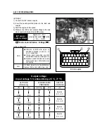
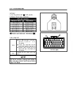
Output voltage
(Input voltage 5 V, ambient temp. 25 °C, 77 °F)
ALTITUDE
(Reference)
(ft)(m)
(mmHg)
kPa
(V)
0
2 000
0
610
760
707
100
94
2 001
5 000
611
1 524
707
634
94
85
5 001
8 000
1 525
2 438
634
567
85
76
8 001
10 000
2 439
3 048
567
526
76
70
ATMOSPHERIC
PRESSURE
OUTPUT
VOLTAGE
Approx.
4.0 ~ 4.3
Approx.
3.6 ~ 4.0
Approx.
3.3 ~ 3.6
Approx.
3.0 ~ 3.3
◈
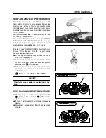
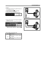
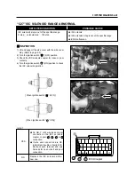
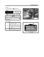
Step 2
1) Connect the IAP sensor coupler.
2) Insert the needle pointed probes to the lead wire
coupler.
3) Start the engine at idle speed.
4) Measure the IAP sensor output voltage at the wire
side coupler (between BL and BW wires).
IAP sensor
output voltage
Approx. 4.0 ~ 4.2 V
when ignition switch “ ” (ON)
(
�
BL -
�
BW )
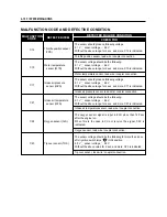
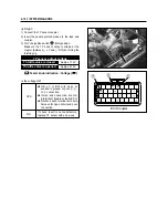
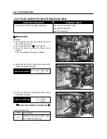
Is the voltage OK?
YES
NO
●
OB, BL or BW wire open or
shorted to ground, or poor
�
,
�
or
⑤
connection.
●
If wire and connection are OK,
intermittent trouble or faulty ECU.
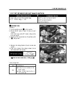
●
Recheck each terminal and wire
harness for open circuit and poor
connection.
If check result is not satisfactory,
replace IAP sensor with a new one.
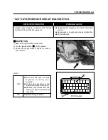
Tester knob indication : Voltage ( )
ECU Coupler
�
⑤
�
Summary of Contents for MS3 125
Page 6: ...NOTE Difference between photographs and actual motorcycles depends on the markets ...
Page 134: ...5 1 FUEL SYSTEM AND THROTTLE BODY FUEL SYSTEM ...
Page 139: ...FUEL SYSTEM AND THROTTLE BODY 5 6 THROTTLE BODY ...
Page 249: ...9 31 SERVICING INFORMATION WIRE AND CABLE ROUTING ...
Page 250: ...SERVICING INFORMATION 9 32 ...
Page 251: ...9 33 SERVICING INFORMATION ...
Page 252: ...SERVICING INFORMATION 9 34 ...
Page 253: ...9 35 SERVICING INFORMATION WIRING DIAGRAM ...
Page 254: ...SERVICING INFORMATION 9 36 ...
Page 257: ...Prepared by 1st Ed DEC 2007 Manual No 99000HP8810 Printed in Korea ...