


Installation - general procedure
1. Install the mounting bracket onto the ceiling.
2. Select the acoustic alarm tone, its volume and the VAD light emission power using the selector (
Altair Flexiplus
only).
3. Install the base sounder on the mounting bracket.
4. Connect the Vega loop to the base sounder.
5. Install the host detector.
6. Set the acoustic alarm tone, its volume and the VAD light emission power on the control panel (
Altair Plus Flexiplus
only).
7. Test the base sounder-host detector assembly.
Mounting bracket installation
1. Pass the loop cables through their bracket’s passage.
2. Set the bracket in the intended installation location.
3. Fix the bracket to the ceiling, using the supplied screws and wall anchors; use the pre-cut holes.
Tone, volume and VAD power selection (Altair Flexiplus only)
Use the internal micro-switches for selecting the acoustical tone, volume and VAD power (if present).
To move the single micro-switches use the tip of a little screw-
driver.
In the tone, volume and VAD power selection tables of this
manual, the micro-switch positioned at the high end is indicat-
ed as “1”, while when at the low end with “0” (picture 3).
1. Set the acoustic tone with the first 5 micro-switches and
referring to table 1.
2. Set the volume with position 6 and 7 micro-switches and
referring to table 2.
3. If applicable, set the VAD power with position 8’s
micro-switch and referring to table 3.
Tone, volume and VAD power selection (Altair
Plus Flexiplus only)
Alarm tone, volume and VAD power (if present), must be set on the control
panel; possible setting options are given in table 1, 2 and 3.
In order to perform this operation, refer to the control panel’s manual.
Installing the device on the mounting bracket
1. Pass the loop’s cables through their device passage.
2. Assemble the bracket together with the device, inserting the pins of the fist
into the corresponding holes of the second.
3. Fix the device to the bracket using the supplied screws.
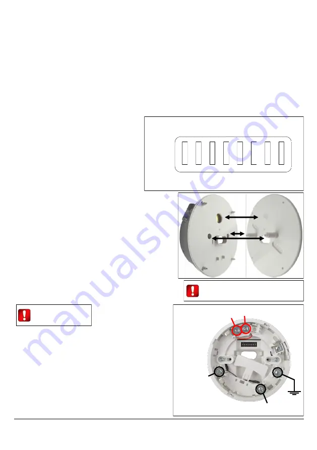
Wiring the base sounder to the Vega loop
Connect the loop’s wires to the adaptor base of the host detector (picture 5); in
any case, refer to the detector manual for further data.
Host detector’s installation
Install the host detector on the base
sounder; refer to the detector’s instal-
lation manual.
Base sounder - host detector testing
1. Alarm and check the detector’s effectiveness as described in its manual.
2. Check that the base sounder’s alarm acoustic signal and volume
correspond as selected.
3. If present, check the VAD’s effectiveness and intensity.
L20-HFIAEB6-1400 (vA.2)
ON
1 2 3 4 5 6 7 8
Picture 3
1
0
Picture 4
Make sure that the bracket’s sound diffuser
cone corresponds to the device’s sound
outlet.
Power off the loop before
performing any wiring.
Picture 5
Loop In
Negative (-)
Loop In
Positive (+)
Loop Out
Positive (+)
Loop Out
Negative (-)
Shield