All electrical connections to the Remote Heater System must be accomplished by a qualified and licensed electrician in
accordance with the National Electric Code and any local codes in effect at the time of the installation. All electrical
connections must be made in accordance with the wiring information contained in this manual or the wiring diagram
included on the inside of the access panel.
The Remote Heater System must be configured to operate at 208-240 volts. Refer to the data label located on the
control box to determine voltage requirements. Connection must be made using copper conductors only. Field provided
conductors and circuit breakers must be sized to accommodate the total amperage load of the equipment. For Power
conductor size, refer to the National Electric Code Table 310-16. For Ground conductor size, refer to the National Electric
Code Table 250-95.
Note
: When determining conductor size, the total length of run must be calculated and sized per the National Electric
Code.
WARNING
– Improper electrical connection or conductor sizing will create the potential for electrical hazard, and may
void the warranty.
CAUTION –
Use only approved pressure-type wire splicing or connectors suitable for the size and type of wiring used.
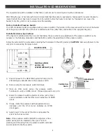
240 VOLT INSTALLATION
1)
Provide the proper voltage and circuit from the service
panel as detailed above.
2)
Open the access panel on the RHS control box to
expose wire connections.
3)
Using copper conductors only, connect input wiring as
shown. A two wire electrical connection plus ground is
required (Line 1, Line 2 and Ground).
4)
Close the access panel when connections are complete
3
ELECTRICAL INSTALLATION
SYSTEM START UP
1)
Turn the thermostat counter clockwise, to the off position.
2)
Fill the spa or hot tub with fresh tap water to the level recommended by the spa manufacturer.
CAUTION
: The Remote Heater System must never be operated without water or serious damage to the heater and/or
Pump may result which will void the warranty.
3)
Check all plumbing for leaks.
4)
With the thermostat in the off position, apply power to the system.
IMPORTANT
: It is important that the pump is operated on high speed for several minutes to assure that all of the air
has been removed from the system before the heater is turned on. Only after full water flow has been achieved should
the thermostat be turned up.
Summary of Contents for HEATMAX Series
Page 2: ......
Page 8: ...85 0116 Rev 5 02 18 ...

