


Maintenance
7
8. Make sure the shaft surface is clean and lightly
oiled. Press by hand the rotating half of the shaft
seal onto the shaft. Be sure the rotating carbon
washer is positioned adjacent to the ceramic seat.
9. Assemble the volute to housing with the four hex
head screws. Position discharge the same as before
in relation to switch clamp.
10. Check HUVA cup seal in volute case inlet. If worn,
replace.
11. Check that the impeller turns freely.
12. Guide the four motor wires up through a common
hole in the bearing plate and place the protective
plastic tube over the four motor wires.
13. Position the o-ring into cap and reconnect the four
motor wires as shown in wiring diagram. The two
green ground wires connect to the pins nearest the
‘G’ marked on the cap.
14. Put oil in the motor housing using only Hydromatic
submersible transformer oil, Part No. 24709110000.
The oil should be about 1/2" above the surface of
the bearing plate
15. Reinstall the top thermoplastic cap, making sure the
o-ring is in position on the cap. Tighten the top six
screws snug, but do not overtighten.
16. Be sure the 1/8" NPT pipe plug is in the top cap.
17. Plug pump into receptacle to test operation. Pump
must run quiet and free of vibration.
NOTE: When replacing top cap with a new one, be sure
the jumper wire and pipe plug are in place. See wiring
diagram. Tether level control to motor housing with float
extended 3-5/8" to 4".
Winding
Locked
Resistance
Max.
Rotor
HP
Speed
V
Ph
in Ohms
Amps
Amps
1/2
1625
115
1
2.0
9.0
17.6
MOTOR RESISTANCE CHART
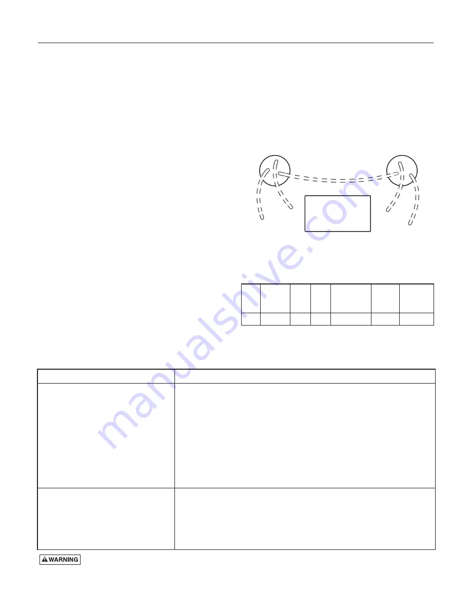
WIRING DIAGRAM
PROBABLE CAUSE
1. Check for blown fuse or tripped circuit breaker.
2. Check for defective level switch.
3. Where control panel is used be sure H-0-A switch is in the AUTO position. If it
does not run, turn switch to the HAND position and if the pump runs then the
trouble is in the automatic electrical system. Have ELECTRICIAN make elec-
trical checks.
4. Check for burned out motor. Occasionally lightning can damage a motor even
with lightning protection.
5. Where plug-in cords are used be sure contact blades are clean and making
good contact. DO NOT USE PLUG-IN CORDS INSIDE A SUMP OR WET
WELL.
6. Level control ball or weight may be stuck on side of basin. Be sure it floats
freely.
1. Check for air lock. Start and stop pump several times, if this does not help it
may be necessary to loosen a union in the discharge line to relieve air lock.
2. Check valve may be installed backwards. Check flow arrow on valve body.
Check shut-off valve. It may be closed.
3. Check vertical elevation. It may be higher than pump can lift. (See pump
curve.)
4. Pump inlet may be plugged. Remove pump to check.
CONDITION
Pump does not run or start when water is
up in tank.
Pump runs but does not deliver flow
Risk of electrical shock. ALWAYS UNPLUG POWER CORDS OR TURN OFF ALL MAIN AND BRANCH CIRCUIT
BREAKERS BEFORE DOING ANY WORK ON THE PUMP. If control panel is remote from pump, disconnect lead wires to motor
so that no one can turn the circuit breaker back on.
TROUBLESHOOTING
Pl
u
g Side for
Piggy-Back S
w
itch
Po
w
er Cord
Side
N
ame Plate
S
u
rface
Black J
u
mper
Motor
(Blac
k)
Motor
(Blac
k)
Motor
(Green)
Motor
(Green)
5
8
93 100
8