Page 22
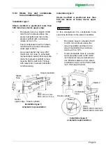
5.5.3 Steam line and condensate
hose installation types
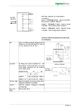
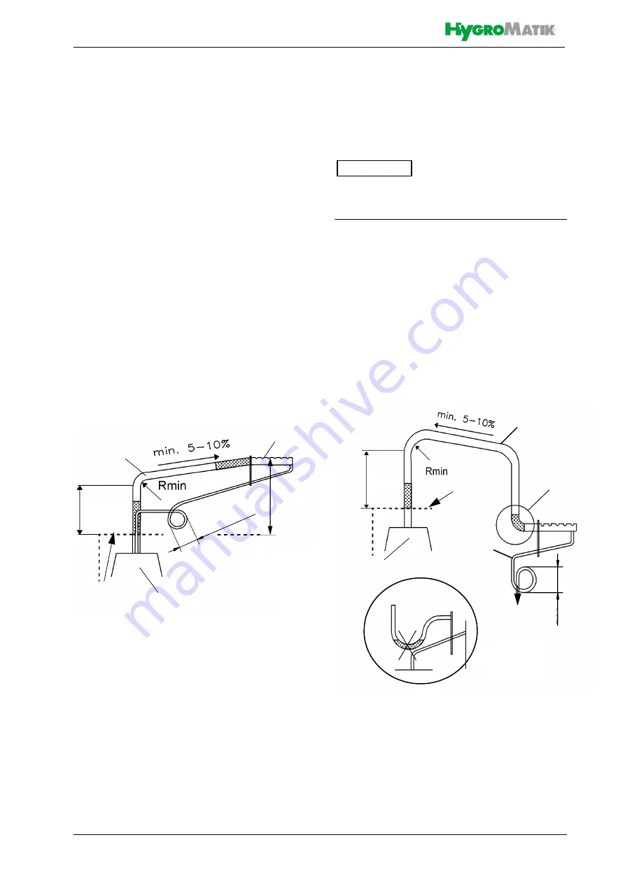
Installation type 1
Steam manifold is positioned more than
500 mm above device upper edge:
»
Run steam hose to a height of 400
mm/16 inch minimum above the
steam humidifier and then to the
steam manifold with a continuos
incline of 5 to 10 %.
»
Feed condensate hose from steam
manifold with a decline into waste-
water pipe or drain.
»
As a steam barrier, lay out a 200
mm/8 inch min. loop (s. schematic
representation below). Minimum dis-
tance from steam manifold to loop
must be 500 mm/20 inch. Fill loop
with water prior to steam humidifier
commissioning.
Installation type 2
Steam manifold is positioned less than
500 mm above or below device upper
edge:
In this arrangement the condensate hose
cannot be fed back to the steam humidifier.
»
Run steam hose to a height of 400
mm/16 mm minimum above the
steam humidifier and then to the
steam manifold with a continuos
decline of 5 to 10 %.
»
Feed condensate hose to a waste-
water pipe/drain with a 200 mm/8
inch diameter loop as a steam bar-
rier. Minimum distance from steam
manifold to loop must be 500 mm/20
inch. Fill loop with water.
Steam cylinder
Steam manifold
Steam
hose
Cond
ensa
te
hose
Installation type 1,
Device
upper edge
schematic representation
500 mm
20 inch
min.
400
mm
16 inch
200
mm
/8‘‘
min
Rmin
DN25: 200 mm/8 inch
DN40: 400 mm/16 inch
Steam cylinder
Steam
hose
Device
upper
Condensate
hose
Drain
Detail „x“
wrong!
Installation type 2,
schematic representation
edge
Detail „x“
Rmin
DN25: 200 mm/8 inch
DN40: 400 mm/16 inch
400 mm 16
inch
200 mm 8 i
nch
Please note
Summary of Contents for FlexLine FLH03
Page 1: ...FlexLine Electric Heater Steam Humidifiers ÁFLH ENKÈ FLH EN E 8881164 Manual ...
Page 45: ...Page 45 11 Declaration of Conformity ...
Page 49: ...Page 49 This page intentionally left blank ...
Page 50: ...Page 50 This page intentionally left blank ...

