9
Operation Procedures
Knowledge of the proper operation of the MX1200 is required to ensure
user safety and efficient performance of the extractor.
SET UP AND OPERATION
1. Electrical Cords:
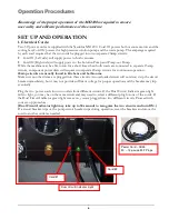
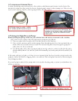
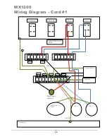
Two 50’ power cords are supplied with the Nautilus MX1200. Cord #1 powers both vacuum motors and the
cooling fan; Cord #2 powers the high pressure solution pump and the waste pump. The amperage required
by each cord requires that the two cords be plugged into two separate 20amp circuits:
•
Cord #1 (Left side) will supply power to both vacuums.
•
Cord #2 (Right side) will supply power to the Solution Pump and Pump-out Pump.
While the machine may be able to run for a short time when both cords are connected to separate 15amp
circuits, component power draw will require two separate 20amp circuits for continuous operation.
20amp circuits are usually found in kitchens and bathrooms.
Make sure no other items are plugged into these circuits. An overloaded circuit will not always trip the circuit
breaker immediately, but it may not provide sufficient voltage for proper operation and the breaker may trip
eventually.
Plug the two power cords into two outlets from different circuits. If the Dual Circuit Indicator green light
fails to light, you may be on the same circuit and may need to select a different plug for one of the cords. If
the Dual Circuit Indicator green light comes on, you are plugged into two different circuits. Proceed with
your set-up procedure.
(Dual Circuit Indicator light may take up to 30 seconds to recognize the two circuits and turn ON.)
If a circuit breaker trips or the pump circuit breaker trips during operation, reset the breakers and move the
cord to another outlet as needed.
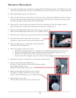
Power Cord – AX33
50’ – 12 gauge M-F Plugs
Cord #1
Cord #2
Dual Circuit Indicator Light
Summary of Contents for Nautilus MX1200
Page 1: ...1 LMANN01 Revised 01 29 2015 Nautilus MX1200 Operating Manual ...
Page 39: ...39 NM5740 AUTO FILL FLOAT VALVE ASSEMBLY ...
Page 41: ...41 Pump Out Pump AP37 PARTS ASSEMBLY ...
Page 42: ...42 1 2 3 5 4 4 6 7 8 9 10 8 12 3 8 9 11 9 23 100 104 2 9 8 39 ...
Page 49: ...49 2 39 1 72 73 73 67 9 30 31 82 83 2 83 82 84 INSIDE SOLUTION TANK BOTTOM VIEW SOLUTION TANK ...
Page 51: ...51 96 88 112 105 93 PUMP OUT PARTS 99 96 91 95 97 9 111 113 117 119 ...
Page 52: ...52 FLOW 81 92 91 99 96 9 97 105 13 14A 14 95 PUMP OUT PARTS 1 39 97 9 119 ...


