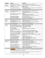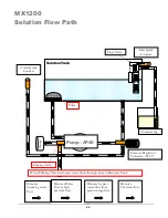
26
NAUTILUS MX1200 SWITCH PANEL:
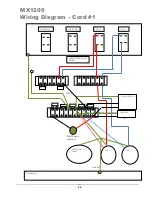
Vacuum #2 – Power from Cord #1.
When the switch is turned to the ON
position power is supplied to the vacuum
motor. (2-Stage Vacuum)
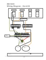
Solution Pump Switch – Power from Cord #2
.
When the switch is turned to the ON position
power is supplied to the solution pump motor.
When not using solution (Extracting Only) do not
turn this switch ON.
Waste Pump Switch – Power from Cord #2.
Do not turn Waste Pump
Switch ON unless a hose is connected to the
Pump-out Outlet port.
For pump protection there is a pressure switch
which will turn the waste pump off if the
pressure in the discharge line gets too high, as it
would if the pump was turned on while the
outlet cap was still in place.
Vacuum #1 – Power from Cord #1.
When the switch is turned to the ON
position power is supplied to the vacuum
motor. (2-Stage Vacuum)
Cooling Fan – Power from Cord #1.
The cooling fan is not controlled by any
switch.
As soon as Cord #1 is plugged in the
cooling fan will turn on to exhaust air from
the base.
Summary of Contents for Nautilus MX1200
Page 1: ...1 LMANN01 Revised 01 29 2015 Nautilus MX1200 Operating Manual ...
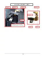
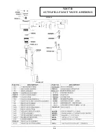
Page 39: ...39 NM5740 AUTO FILL FLOAT VALVE ASSEMBLY ...
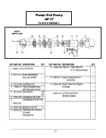
Page 41: ...41 Pump Out Pump AP37 PARTS ASSEMBLY ...
Page 42: ...42 1 2 3 5 4 4 6 7 8 9 10 8 12 3 8 9 11 9 23 100 104 2 9 8 39 ...
Page 49: ...49 2 39 1 72 73 73 67 9 30 31 82 83 2 83 82 84 INSIDE SOLUTION TANK BOTTOM VIEW SOLUTION TANK ...
Page 51: ...51 96 88 112 105 93 PUMP OUT PARTS 99 96 91 95 97 9 111 113 117 119 ...
Page 52: ...52 FLOW 81 92 91 99 96 9 97 105 13 14A 14 95 PUMP OUT PARTS 1 39 97 9 119 ...

