


2.18
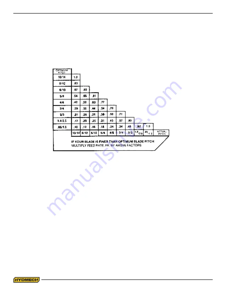
If the saw is fitted with a blade coarser than optimum (e.g.: 1.4/2.5 TPI) we can still use the graph, but we go to the 1.4/2.5
curve. As a result we find that the FEED RATE is decreased to 1.3 in/min (133mm/min) for this blade. If however, the
machine is fitted with a finer than optimum blade (e.g. 3/4 TPI) we use the graph for the optimum blade as before, and
then use a multiplier given by the table below.
Optimum Vs Actual Blade Pitch
ADDITIONAL CUTTING SETUP EXAMPLES
EXAMPLE # 2
Material:
Round Steel Tube SAE 4320 - Hardened to 35 RC (325 Bhn )
Dimensions - 6” O.D. x 4” I.D. (150mm O.D. x 100mm I.D.)
Step 1
Effective Material Width: 4 1/2” (.75 X 6) 114mm (19 x 6)
Step 2
Feed Force limit setting for 6” Diameter material (Refer to Feed Force Limit, Setting in Step 2)
Step 3
Optimum blade pitch (TPI): 3/4 T. P. I.
Actual blade pitch on the saw: 4/6 T. P. I.
Step 4
Optimum blade speed for 4 1/2” effective 225 ft/min (70m/min) material width
Blade speed reduced by hardness factor: 225 ft/min X .60 = 135ft/min (70m/min x .60 = 42m/min)
Step 5
Feed Rate for 3/4 TPI blade: 1.8 in/min (45mm/min)
Feed Rate for 4/6 TPI blade: 1.8 in/min X .70 = 1.3in/min
(reduced by finer than optimum blade pitch factor) (45mm/min x .70= 31.5mm/min)
FEED RATE, continued
Summary of Contents for M16A
Page 2: ...2 ...
Page 3: ...2 ...
Page 38: ...2 20 ...
Page 55: ...4 1 ELECTRICAL SCHEMATICS SEE PDF ON ATTACHED CD SECTION 4 ELECTRICAL ...
Page 56: ...4 2 ...
Page 61: ...6 2 ...
Page 68: ...7 7 AUTOMATIC MODE SCREEN Fig 8 ...
Page 72: ...8 2 M16A LAYOUT ...
Page 74: ...8 4 M20A LAYOUT ...
Page 76: ...9 2 ...


