


11
A discharge check valve must be placed between
the aftercooler and the discharge receiver. This is
especially important on booster compressors, as
high pressure gas (or air) may leak back through the
compresor to the suction side of the system, causing
dangerously high pressures in the suction side
receivers, piping, etc.
On initial start-up of the compressor, bubble test all
piping connections for leaks with a soap-water solution.
All piping must be leak free.
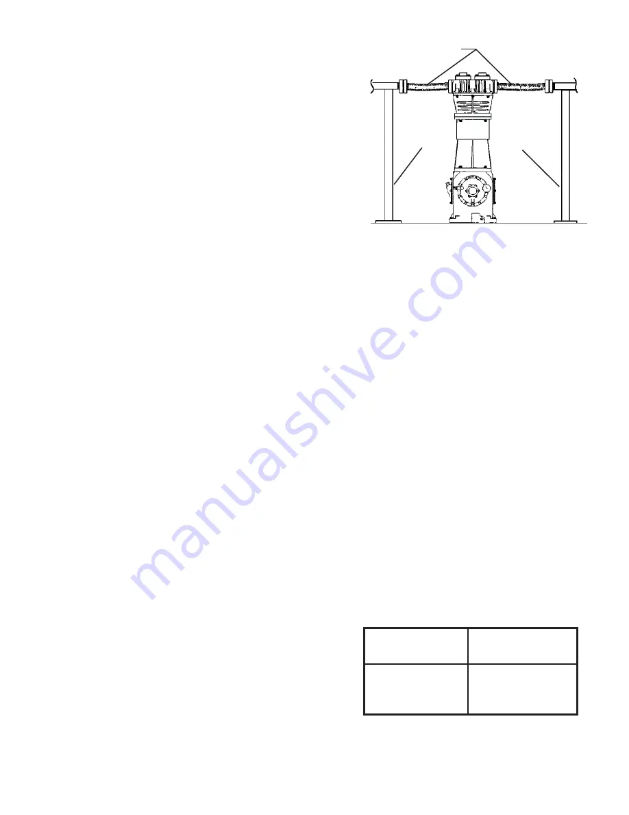
Flexible expansion joints must be placed within 36
inches of the compressor to help compensate for
expansion/contraction of the pipes, as well as isolate
the vibration of the compressor from the rigid piping.
All piping must be adequately supported to ensure no
piping loads are placed upon the compressor (see
Figure 5). Failure to do so may cause a dangerous
break in the rigid pipe caused by vibration in the
piping.
All piping must be compatible with the gas being
compresssed, and must be rated above the working
pressure of the system.
Compressor
Horsepower
1-3
5-15
20-50
Receiver size
Gallons / HP
20-40
15-20
8-12
be rated for the working pressure of the inlet gas, and
protected with a properly sized safety valve set at 20
to 30 PSI above the maximum operating pressure but
below the maximum allowable working pressure of
the pipe.
An inlet
fi
lter must be placed in-line with the inlet, to
ensure clean gas (or air) to the booster. The
fi
lter
should be a 1.0 micron or better, coalescing type,
suf
fi
ciently sized for twice the full
fl
ow of the booster
with minimal pressure drop. Inlet
fi
lters should be
installed on the upstream side of an inlet receiver to
prevent pulsation damage. The inlet receiver and
piping must be cleaned of any foreign residue before
compressor startup. Unless otherwise indicated, air
boosters and gas compressors do NOT come with an
inlet gas
fi
lter. Damage to the machine will occur if
contamination is drawn into the booster compressor
and will void the warranty!
Hycomp air boosters and gas compressors require
an inlet receiver to be installed just upstream of the
booster compressor. See RECEIVERS (Air Boosters
& Gas Compressors) for additional sizing details. See
Figure 4 for additional details.
Compressors are not designed to pump any liquids.
Liquids are non-compressible and even the slightest
amount of liquid can cause high-impact stresses
resulting in serious damage to the compressor. The
use of a liquid trap in the suction line is required where
the presence of entrained liquids in the suction gas is
a possibility.
DISCHARGE PIPING
Recommended practice is to have a compressor
aftercooler, discharge safety valve, discharge check
valve, and an air receiver. To prevent undesirable
pressure drops in piping, pipe size should be
increased one size for each 100 feet of run. Sweat
type copper
fi
ttings, when compatible with the gas
being compressed, will give much less pressure loss
than the equivalent size steel pipe. All horizontal pipe
runs should be sloped away from the compressor at
about one quarter inch per foot. All low points in the
piping system should have a drain leg to catch any
accumulation of condensation in the piping.
It is extremely important that a properly sized safety
valve, set at 10% or 20 to 30 PSI above the maximum
operating pressure but below the maximum allowable
working pressure of the system components, be
placed at the discharge receiver and upstream of the
aftercooler. Never place a line valve in the discharge
piping between the compressor discharge and the
safety valve.
Flex Connectors
Rigid Pipe
Support
Rigid Pipe
Support
Table 1: Receiver Sizing for Ambient Air
Compressors
Figure 5: Piping Connections