background image

Problem: Draft blower will not run. NOTE: Verify that the wall thermostat is in the 

“HEAT” position, and make sure batteries are installed.

• Defective rocker switch on control

center.

• Replace rocker switch.

Possible Causes:

Remedies:

• Defective wall thermostat.

• This can be checked by turning the thermostat to a temperature

setting that is higher than the temperature in your home. If the draft

blower does not operate, the thermostat may be defective. Replace

if necessary.

• Move switch on wall thermostat to the “HEAT” position.

• Replace relay.

• Replace draft motor.

• Wall thermostat is in the wrong

position.

• Defective relay in transformer.

• Defective draft motor.

4.

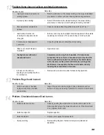
Problem: Excessive dirt accumulation surrounding air registers in the home.

Possible Causes:

Remedies:

• Furnace is not connected to

return air duct and is drawing

dirt from furnace room floor and

disbursing it throughout home.

• Connect to return air duct system.

• Install filter box on furnace. Install filter in filter box.

• Filter box not installed, or no filter

in filter box.

5.

Problem: Smoke from the fire chamber is puffing back through the forced draft motor.

• Furnace is not connected to

return air and is drawing smoke

fumes from the flue.

• Connect to return air duct system. Or room may be too airtight, refer

to “Location and Installation” section on page 3.

Possible Causes:

Remedies:

• Excessively long run of stove

pipe from furnace to flue.

• Relocate the furnace so the horizontal run does not exceed 5 feet

and has a 2 inch rise per foot.

• The run should not contain more than 2 elbows.

• Replace with a larger flue providing a minimum of 50 square

inches but not more than 100 square inches of draft area. If the

flue is within  these specifications, check the draft with a draft gage

(manometer). Your flue should provide a minimum of .04 water

column inches and a maximum of .08 water column inches.

• Too many elbows.

• Insufficient flue size.

6.

• Review wiring diagram. If unit is wired correctly, seek professional

assistance.

• Improper wiring.

19

Summary of Contents for Shelter Furnace SF1000

Page 1: ...G INDOOR FURNACE MODEL SF1000 Manufactured by Shelter Furnace 10950 Linpage Place Saint Louis MO 63132 1 800 875 4788 MADE IN USA Revision II June 2017 Certified to UL391 Sept 2010 CSA B366 1 2014 Con...

Page 2: ...This Page Intentionally Blank...

Page 3: ...ut Wood that is properly cut and stored to dry will produce more BTUs and higher heat output than wood that has a higher moisture content Wood with higher moisture content will create creosote in the...

Page 4: ...ve in perfect condition Any visible damage should be noted on the freight bill at the time of delivery If upon unpacking your Shelter Furnace you find damage has occurred during transit notify your su...

Page 5: ...12 14 14 14 15 15 15 15 15 Furnace Diagram with Parts List 17 Blower Motor Assembly Diagram 18 Wiring Diagram 19 Troubleshooting 20 Warranty Information 25 DOUBLE CHECK TO MAKE SURE YOU HAVE RECEIVED...

Page 6: ...cognized safety standard and within clearances specified on the nameplate When in a parallel installation the static pressure of the central furnace plenum may not exceed 0 15 water column inches and...

Page 7: ...coming off the top of the appliance can only go up or horizontal to connect into the main supply duct Never run the plenum down as this will create a heat buildup in the furnace causing the blower to...

Page 8: ...your convenience your Shelter Furnace has been factory assembled and the electrical control assembly pre wired 1 Fasten the right and left side angle brackets to the circulation blower using 4 20 bolt...

Page 9: ...ke sure the filter box is tightly pressed to the back of the furnace Use 4 1 4 bolts included to firmly attach the filter box to sides of furnace Filter Box 1 4 Bolts Panel A Panel B Panel C Panel A 8...

Page 10: ...should point toward the furnace to form drip free connections thereby reducing the possibility of creosote leakage from the joints Installing a non UL listed heat reclaimer in the pipe is not recomme...

Page 11: ...discharge When using a brick chimney you must line the entire chimney with stainless steel liner The liner must be 6 for the SF1000 The diameter of the chimney stack should be consistent throughout th...

Page 12: ...gether The return air system should be a minimum of 10 larger than the heat outlet to readily transfer the cold air back to the furnace Avoid using 90 elbows in duct runs 45 elbows provide better airf...

Page 13: ...t Firewood should be stacked to provide a free flow of air between the logs thus allowing more rapid seasoning of the wood If wood is stored outdoors it should be completely covered year round to prot...

Page 14: ...on of these substances may release harmful toxic gases Do Not Burn Garbage Lawn clippings or yard waste Materials containing rubber including tires Materials containing plastic Waste petroleum product...

Page 15: ...firing your furnace This type of occurrence is usually symptomatic of heat demands in excess of furnace capacity Contact an authorized professional to determine if your Shelter Furnace has been improp...

Page 16: ...With the cover closed no air is introduced into the firebox then the fire dies preventing the furnace from possible overheating and damage Creosote Formation and Need for Removal When wood is burned...

Page 17: ...d will produce a higher BTU output and a longer burn time Refer to the nameplate on furnace for additional information WARNING RISK OF FIRE Do not operate with the flue draft exceeding 08 water column...

Page 18: ...SEMBLY FCE FDA 3 1 FURNACE SHELL FC10SHELL 4 2 SIDE PANEL ASSEMBLY FCE 10SP 5 1 BLOWER ASSEMBLY FC3SPMOTOR 5a 1 BLOWER MOTOR FCDD037P 5b 1 BLOWER HOUSING FCBH 6 1 FILTER BOX BOTTOM WAF FBB 7 2 FILTER...

Page 19: ...ram PARTS LIST DESCRIPTION QTY ITEM BLOWER WHEEL 1 1 BLOWER HOUSING 1 2 MOTOR CAPACITOR 1 3 BLOWER MOTOR 1 4 2 1 2 3 PARTS LIST DESCRIPTION QTY ITEM BLOWER WHEEL 1 1 BLOWER HOUSING 1 2 MOTOR CAPACITOR...

Page 20: ...A B B FAN LIMIT CONTROL WALL THERMOSTAT 120V AC 24V AC TRANSFORMER RELAY DRAFT BLOWER MOTOR BLOWER MOTOR 120V AC POWER SUPPLY WHITE BLACK GREEN BLACK WHITE RED RED RED YELLOW BLACK ORANGE WIRING DIAGR...

Page 21: ...r vibrates during operation Screw on squirrel cage is not tight Check squirrel cage alignment and position so that it does not drag on the housing during rotation then tighten the screw sufficiently t...

Page 22: ...rn air duct system Install filter box on furnace Install filter in filter box Filter box not installed or no filter in filter box 5 Problem Smoke from the fire chamber is puffing back through the forc...

Page 23: ...nstall flue gas thermometer and maintain stack temperatures between 300 and 400 F See 9 Insufficient chimney draft 8 Improper connection in stove pipe causing air leakage or a structural defect in the...

Page 24: ...truction outside chimney such as a tree Flue is located too close to the peak of the roof or does not rise above it to provide the proper draft Backdraft damper is in the closed position 9 Problem Odo...

Page 25: ...of insect infestation such as burrows or holes avoid using if possible Do not store wood indoors Possible Causes Remedies 13 Problem Circulation blower will not turn on Defective fan limit control Che...

Page 26: ...This Page Intentionally Blank 23...

Page 27: ...ick and door gaskets are excluded from this warranty In order to exercise the aforementioned warranty a certified professional must determine the appliance part to be defective He or she must submit a...

Page 28: ...This Page Intentionally Blank...

Reviews: