Installation and Maintenance Manual
18
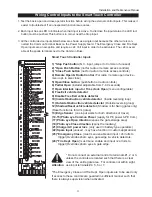
b. Press the Program Menu button and watch the LCD scroll the system data, or press the Pro-
gram Menu key a 2nd time to skip the scroll. The scrolled data displays the information in the
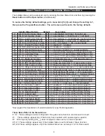
table on page 22.
c. The LCD display scroll will stop at the menu item for the automatic close timer setting [Ct __].
This is the first item in the User Menu.
d. To access the more detailed Installer Menu, the system must first be in the User Menu, and then
simultaneously press the Reset button and the Open button. The LCD will change to display the
UL usage class menu item [uC __] This is the first item in the Installer Menu.
4. Pressing the Program Menu button when the User or Installer Menu is not blinking will return the
system to the Run Mode.
Installation Configuration for Smart Touch Controller
Setting Operator Handing and Usage Class
1. Connect the hydraulic hoses to the quick couplers on the pump in order to configure left or right hand
opening function (as viewed from the secured side of the gate). There is a label near the connection
point describing this procedure. Also see the illustration on page 12. If the hoses are connected
incorrectly, the gate will run backwards (close when open button is activated) and this may trigger an
error [Err 1] on the LCD display. (The Reset button must be pushed if this happens).
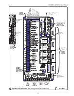
2. Turn on the power switch and observe that the LCD will first show the software version, and then stop
at a steady display within two seconds. If the display reads [uC 0] go to step 3. If the operator has
previously been configured, the Installer Menu must be accessed in order to reach the system configu-
ration menu items: see step #3d at the top of this page.
3. When turning on the power for a new machine, the LCD display directly enters the Installer Menu at the
[uC __] menu item, which is for selecting the user class as defined by UL. Select [uC 1] - [uC 2] -
[uC 3] or [uC 4] depending upon the use application. See Section 4, page on page 31, for UL usage
class definitions.
4. To set the operator handing, use the “Next” button and move one click down the menu to item [Sh __]
Enter r for right hand or L for a gate that opens to the left. Never alter the limit switch mounting or
change the order of their connection to the controller board. At this point you should exit the Installer
Menu, by pressing the Program Menu button. The LCD display jumps to the close timer [Ct__] setting
in the User menu, which may now be set. Either press the Program Menu button again to exit to
normal run mode or set the close timer by the same programming sequence described at the previous
page.
5. Note that the Installer menu cannot be exited by any means until the selection for UL usage
class [uC __] and the selection for gate handing [Sh __] have been entered.
6. Test for normal function of the gate operator, with the wheels unclamped, by running it both open and
closed from the pushbuttons on the membrane switch pad. Neither limit switch should be triggered at
the start of this test or an alert [ALE6] may trigger because the control did not sense gate motion. If
this occurs a new input will restart the motor.


