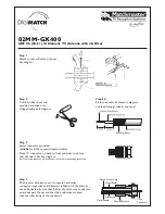
( ) Place the antenna base under the Mast Saddles and align the end of the base with the
edge of the mounting plate as shown in Figure I.
( ) Tighten the (4) bolts to hold the antenna base in place. Do not over-tighten the nuts.
( ) Place the (2) U-bolt assemblies (UB) into the holes in the antenna mounting plate as
shown in Figure I. Leave nuts loose until installation of the antenna.
TASK IX
Capacity Hat Assembly
( ) Refer to Figure J for assembly of the four Capacity Hats.
( ) Rotate the AV640 Coil Assembly (Ll) so the top end of the 17 meter stub is away
from the AV640 Coil Strap as shown in Figure J. To rotate the coil assembly, loosen
the lower coil hose clamp (HC 1). Tighten hose clamp when finished.
( ) Place (8) 6-32 x 3/8" screws (S1) and (8) 6-32 Keps nuts (Ni) in each Counterpoise
Ring assembly on the AV-640 Coil Assembly (LI). Leave the nuts loose so that the
spokes can be slid between the rings.
( ) There are spokes of lengths 6", 12", 24",36" and 48". Place the spokes in the ring
assemblies as shown in Figure J. The shorter spokes will be on the bottom end of the
coil and the longer spokes will be on the upper end of the coil. The 40" spokes are
spares. Tighten all hardware on the ring assemblies. The formed ends of the spokes can
be positioned in any direction.
( ) NOTE: For tuning 15, 20 & 30 meters, the lengths of a spoke is adjusted as shown in
Figure J, (1,15, L20 & L30). Since the AV640 has a broad low VSWR, it is suggested the
AV640 spokes be installed at their initial lengths of 6", 12", 24" & 36". If any of the bands
(15, 20 & 30 meters) are resonant too low in frequency, one of the corresponding spokes
can be pruned.
Only one spoke will require pruning.
Please refer to the Tuning section on
Page 17 and Figure J for more information.
Installation
The AV-640 antenna should be mounted at least 8 feet above ground. The main reason for
this minimum height is safety. The AV-640 will work well at a minimum height of five
feet but precautions from dangerous voltages must be taken.
Always have help for the installation process. Do not attempt to install the antenna
alone. Review the requirements for Antenna Location and safety precautions regarding
Power Lines earlier in this manual.
1
Summary of Contents for AV-640
Page 20: ...FIGURE A AV 640 Center Radiator Assembly ...
Page 21: ......
Page 22: ...FIGURE C Installation of AV 640 Stub Base Brackets ...
Page 23: ...FIGURE D Installation of Stub Insulators ...
Page 24: ...FIGURE E Installation of Stub Insulators ...
Page 25: ...FIGURE F Stub Assembly ...
Page 26: ...Figure G Stub Installation ...
Page 27: ......
Page 28: ...M U FIGURE I AV 640 Antenna Mounting Plate Assembly ...
Page 29: ......