background image

START-UP & ADJUSTMENTS

MI35.2505

02JAN96

Do NOT operate system without having the ground

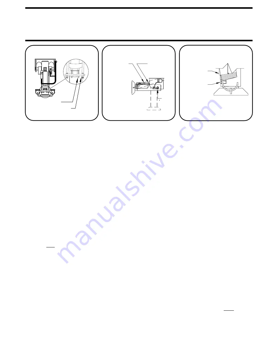
FIGURE 10

16000# JACK

FIGURE 11

SET SCREW

ADJUSTING 

HEAVY DUTY 
LEVELING 

CAP

UNITS

ADJUSTING NUTS

SET SCREWS

FIGURE 9

9000# JACK

LOWER
ADJUSTING

LOW PROFILE

STANDARD &

UNITS

NUT

UPPER
ADJUSTING
NUT

STOP

A. HYDRAULIC START-UP

1. PRIMING PUMP 

4-LEVER:
turn the master switch on. Move any lever on the manual
system to the EXTEND postion. The lever must be moved
to the fullest extent of its travel. This should be done in 3-
second intervals until the pump is primed. This can be de-
termined by a lower pitch sound from the pump. Extend the
two front jacks until they bump the ground, then RETRACT and

Check the system for hydraulic leaks.

Check that the correct jacks are operating as each lever is
operated.

Refill hydraulic tank to within 1" of the top after all jacks have
have been operated.

B. JACK ADJUSTMENTS

Horizontal stop is adjusted by turning the set screws located
just inside the cable locknuts. The jack can be adjusted down
to provide clearance for objects which may interfere with the
operation of the jacks. The horizontal stop must be adjusted to
provide clearance in case the jack extends in the horizontal posi-
tion. The jack must be able to fully extend in the horizontal posi-
tion without interfering with suspension components, tanks,
etc.

Each jack should be checked to be sure that it is vertical when
it swings down. To do this retract all jacks, then extend each
jack until it is close to but not touching the ground. Each jack

it can be adjusted by loosening the lower actuator nut and
tightening the upper actuator nut. (FIGURE 10) If the jack

provide clearance for objects which may interfere with the
operation of the jack (FIGURE 10). The stop must be adjusted
so that the jack can be fully extended in the horizontal  pos-
ition without interfering with suspension components or tanks,
etc.

If the jack stopped short of being vertical,

the jack went beyond vertical, loosen the set screw and turn
the adjusting cap counterclockwise. After each counterclock-
wise adjustment, the weight of the coach must be applied to
the jack to make the adjustment effective. Do NOT adjust cap
more than one turn without cycling the jack (FIGURE 11). The 
horizontal stop on the heavy-duty jack is adjusted by adding
washers under the urethane stop.

The horizontal stop can be adjusted up or down in the slot to

loosen the set screw and turn the adjusting cap clockwise. If

wire grounded properly to the chassis.

Consult the respective operator’s  manuals for specific operat-
ing instruction for the system being installed.

6000# JACK

PART IV

To prime the pump turn the ignition key on, then

NOTE:

1. 6000# JACKS:

2. 9000# JACKS:

3. 16000# JACKS:

- KICK DOWN JACKS ONLY

If the jack stopped short of being vertical

must be adjusted so it can extend in the horizontal position
without interfering with any suspension components, tanks,
etc.

goes past vertical reverse the process.

refill the tank.  Care should be taken not to run the pump
out of fluid as it may damage the pump.

Always make the vertical adjustment first.

If the vertical adjustment is changed at any time, be sure
to check the horizontal adjustment.  Vertical adjustment is
changed by adjusting the locknuts on the actuator cable.
(FIGURE 9) If the jack stopped short of vertical, tighten the
locknuts off.  If the jack goes past vertical, back the lock-
nuts off.  Be sure to adjust each nut the same number of 
turns.

Summary of Contents for 100 Series

Page 1: ...R CRAWLING UNDER VEHICLE BLOCK FRAME AND TIRES SECURELY BEFORE CAUTION HYDRAULIC 5AMP FUSE LR LR WARNING H CORPORATION LF H LF W LEVEL RF R RF OFF LEVEL RF RF UNDERSTAND OPERATOR S MANUAL BEFORE TIRES OR CRAWLING UNDER VEHICLE USING BLOCK FRAME AND TIRES BEFORE REMOVING HWH HYDRAULIC LEVELING CAUTION EXTEND WARNING LEVELING STORE LR LR LF LF 5 AMP FUSE OFF RR RR LEVEL 100 SERIES 110 SERIES 24OCT05...

Page 2: ...NOTE HWH Corporation assumes no liability for installation of this product CAUTION READ THE ENTIRE INSTALLATION PROCEDURE BEFORE STARTING INSTALLATION BLOCK FRAME AND TIRES BEFORE CRAWLING UNDER VEHICLE DO NOT USE LEVELING JACKS OR AIR SUSPENSION TO SUPPORT VEHICLE WHILE UNDER VEHICLE OR CHANGING TIRES VEHICLE MAY DROP AND OR MOVE FORWARD OR BACKWARD WITHOUT WARNING CAUSING INJURY OR DEATH DO NOT ...

Page 3: ...structure If the vehicle is equipped with a full air bag suspension an air dump system must be used Vehicles with supplemental air bags or suspensions such as JET AIR do not Are all components necessary for the installation including mounting brackets hardware kits Does the vehicle need exhaust work done before the jacks are installed Does the vehicle have a good set of batteries that are fully ch...

Page 4: ...ounting heights CAUTION VEHICLE WILL RAPIDLY DROP SEV ERAL INCHES IF AIR BAGS DEFLATE DEFLATE AIR BAGS BEFORE WORK ING UNDER THE VEHICLE 4 DEFLATING AIR BAGS the vehicle s frame must be securely blocked The air can be released by disconnecting the air line between the height control valve and the air bag Usually the fitting at the height control valve is easiest to get to See the SUSPENSION AIR DU...

Page 5: ...nents on the vehicle such as axles springs air bags steering linkage etc Kick down jacks may need to be adjusted to allow full extension of the jack in the horizontal position HWH Corporation assumes no liability for damages to the vehicle or jack resulting from jack extension in the horizon tal position Jacks must NOT be exposed to high temperatures such as exhaust pipes If exhaust pipes need to ...

Page 6: ...6 75 MIN 15 5 MAX 17 5 21 5 MIN 2 0 MAX 4 0 MIN 16 5 MAX 18 0 22 0 MIN 3 0 MAX 4 5 MIN 17 5 MAX 19 0 23 5 MIN 3 0 MAX 4 5 MIN 19 75 MAX 21 25 24 75 MIN 3 0 MAX 4 5 8 0 6 5 8 5 8 5 9 0 8 5 8 0 12 5 1 5 4 5 1 5 4 5 1 5 4 5 4 0 4 0 Dimension E is the suggested mounting height Dimension G is the suggested ground clearance when the jack is vertical but not extended If using kick down jacks on vehicles ...

Page 7: ...00 X 13 AP9823 16000 X 16 8 0 9 4 4 9 6 0 6 0 4 9 4 9 8 0 9 4 6 0 9 4 6 0 9 4 6 0 7 0 12 0 7 0 8 0 MIN 10 0 MAX 8 0 MIN 10 0 MAX 8 0 MIN 10 0 MAX 8 0 MIN 10 0 MAX 8 0 MIN 10 0 MAX 8 0 MIN 10 0 MAX 8 0 MIN 10 0 MAX 8 0 MIN 10 0 MAX 8 0 MIN 10 0 MAX 13 0 13 0 13 0 13 0 13 0 13 0 16 0 16 0 16 0 16 0 22 5 22 5 20 0 21 7 25 8 21 9 25 9 22 0 28 5 21 0 23 5 17 0 17 0 21 0 17 0 17 3 17 5 17 5 14 5 0 0 0 0...

Page 8: ...ts Keep welding cables away from electrical systems 5 SPARTAN Disconnect both battery cables ALWAYS DISCONNECT THE GROUND CABLE FIRST Attach the welding ground to the part to be welded Do not use suspension components as ground points Keep welding cables away from electrical systems HWH Corporation does not suggest welding brackets to the frame rails However if any welding is done such as modifyin...

Page 9: ...d screws If necessary the sensing unit and harness may be unplugged to ease installation This may be done by removing This may be done by removing the hole cover and cover plate until sensing unit and harness are plugged in and hole cover is replaced Caulk around the underside of the 3 LOCATING AND MOUNTING THE PUMP 4 HYDRAULIC HOSES Do not attach hoses or wiring to any fuel or CAUTION When connec...

Page 10: ...n the front of the jack After connect ing the hose to the fitting the hose should be clamped with a 1 4 bolt to the left side of the pivot bracket Be sure the hose is snug against the jack in the retracted horizontal position Route the hose around the left pivot then across the back side of the cylinder and connect to the actuator fitting Attach the hose to the pivot bracket using a hose clamp The...

Page 11: ... dash in a location highly visible to the driver This light will warn the driver if any of the jacks are down when the ignition is turned to ON Drill a 1 2 hole at the desired location Be sure to check for wires or other devices behind the surface before drilling When installing the light itself make sure the ignition is in the OFF position With the ignition on 12 can be present at the warn ing li...

Page 12: ...l wires are securely clamped or tie wrapped 4 Check oil level before operating the system 5 Check Hydraulic circuit a Hoses are connected to corresponding valves and jacks b All fittings for tightness 6 Check Wiring circuits a That color coded wires are hooked properly b All cables are securely fastened c All ground wires are securely fastened to the ground stud PART III ...

Page 13: ...MPONENT INSTALLATION MI35 2025 06OCT95 PART III FLUSH MOUNT DASH PANEL TEMPLATE DASH LINE INDICATES OUTER BEZEL USE ACTUAL BEZEL FOR POSITIONING MOUNTING HOLES 0 4883 3 610 3 250 3 1240 4 6240 5 110 4 750 ...

Page 14: ...or nut FIGURE 10 If the jack provide clearance for objects which may interfere with the operation of the jack FIGURE 10 The stop must be adjusted so that the jack can be fully extended in the horizontal pos ition without interfering with suspension components or tanks etc If the jack stopped short of being vertical the jack went beyond vertical loosen the set screw and turn the adjusting cap count...

Page 15: ...wn in the level position START UP ADJUSTMENTS D LEVELING SENSING UNIT ADJUSTMENT to be sure that the wiring is correct and that all lights are functioning properly 3 The yellow lights indicate that the corresponding corner of the coach is low any one of the jacks is in the vertical position and the ig nition key is in the ON position After all adjustments are made 1 Run the system several times 2 ...

Reviews: