background image

PART III

MI35.2015

25AUG95

5. WIRING: Refer to the appropriate electrical  diagram for

wiring. Any wire or cable in the interior of the coach is to be
protected by fusing. All wire insulation should be rated 125
deg. Celsius (257 deg. F). Check applicable RVIA or other
code for detailed fusing and wiring information. Protecting 
all wires and cables by fusing is desirable.

A #2 battery cable is supplied with most systems to connect
the pump to the battery or a battery junction post. If a different
cable is used it must be able to carry 200 amperes. If fusing
is required, use a 200 ampere fuse. The fuse should be placed
near the power source. Never connect a fuse directly to the
battery or place it in the battery box where an electrical spark
can cause the battery to explode. If power is taken directly 
from the battery, the fuse should be at least 18" from the bat-
tery. A fuse kit is available from HWH Corporation.

Wiring harnesses supplied are usually adequate for most 
installations. Harnesses are loomed at the factory. All con-
nections are plug in type except for pump relay which has
ring terminal connections and the power supply for the panel.
That is a field connection made by the installers.

If lengthening or shortening the harness is necessary it is
suggested that all connections be soldered and protected
with shrink tube. If other connection devices are used they
must be sealed to prevent deteriation of the connection.
Grease-filled weather resistant crimp on butt connectors are
available .

Packard Connectors are marked with A & B for wire

connections. This cannot be mixed up. Maintain correct wire
size and color when altering harnesses.

Master Warning Light/Buzzer connections are done by the
installer. Route all wiring away from all heat sources and  pro-
tect against sharp edges. Check that jacks can pivot properly
without cutting or stretching wire harnesses or connections.
All grounding connections are supplied by HWH Corporation
and all grounding should be done at the supplied ground stud.
(Refer to PUMP RELAY AND PANEL CONNECTION DIAGRAM).
Coat all exposed electrical connections (battery cable ends,
pump solenoid terminals, grounds, etc.) with a protective
sealant such as Kraylon 1307.

6. THE MASTER WARNING LIGHT/BUZZER:
Warning Light should be used with all systems. A buzzer must
be used with systems using straight acting jacks.The Master
Warning Light should be mounted in the dash in a  location
highly visible to the driver. This light will warn the driver if
any of the jacks are down when the ignition is turned to "ON".
Drill a 1/2" hole at the desired location. Be sure to check for
wires or other devices behind the surface before drilling. When
installing the light itself, make sure the ignition is in the "OFF"
position. With the ignition on  +12 can  be present at the warn-
ing light.

When using a buzzer, the +12 power should come from the
"ON" side of the ignition switch. The power for the panel should
come from the "ACC" side of the ignition switch. (Refer to the
MASTER LIGHT/BUZZER CONNECTION DIAGRAM).

With all wiring complete, the light plate  (100 Series System),
or cover plate (110 Series) may now be mounted.

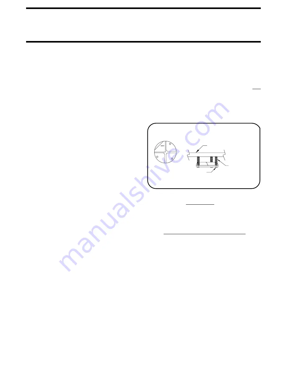
7. MOUNTING THE SENSING UNIT:
can be mounted above or below the surface as long as the
"This Side Up" sticker (FIGURE 8) is facing up and the "Rear"
arrow is pointing to the rear of the coach. The sensing unit
must be mounted to a solid surface that will not flex. Do NOT
mount the sensing unit near any heat-emitting items. Outside
of the frame rails is preferred. The sensing unit must be at
least 12" away from exhaust pipes or other high temperature
components, and must not be in line of sight from these high
temperature components.

A Master

8. FLUIDS: Use Mercon, Multipurpose or Dextron automatic
transmission fluid. DO NOT USE brake fluid or hydraulic
 jack fluid. Use of these fluids can damage seals. The hydraulic
tank should be filled to within 1" from the top.

Air Dump - Optional

The air dump feature is used only on coaches with full air bag
suspension, not on coaches with spring suspensions and air
booster bags.

Most coaches have three height control valves; one for the
right rear air bag, one for the left rear air bag, and one for
the front two air bags, OR one for the two rear bags, one for
left front air bag, and one for the right front air bag.

An air dump solenoid valve must be teed into the air line be-
tween each height control valve and the air bag it controls.
(See the Air Line Connection Diagram).

On the 100 and the 110 Series, the air dump signal is on the
yellow wires coming from the control panel. There is one
connection at the front of the vehicle and one at the rear. A
Tee adaptor is supplied with the control system. This will con-
nect two dump valves to one harness connection at the front
or rear of the vehicle. (Refer to Electrical Connection Diagram
With Suspension Air Dump.)

COMPONENT INSTALLATION

NOTE:

The Level Sensing Unit

SURFACE

MOUNTING

BELOW THE SURFACE MOUNTING

SCREWS (3)

REAR

THIS 

SIDE

STICKERS

ON TOP

UP

FIGURE 8

LEVEL SENSING UNIT

SPRINGS (3)

Summary of Contents for 100 Series

Page 1: ...R CRAWLING UNDER VEHICLE BLOCK FRAME AND TIRES SECURELY BEFORE CAUTION HYDRAULIC 5AMP FUSE LR LR WARNING H CORPORATION LF H LF W LEVEL RF R RF OFF LEVEL RF RF UNDERSTAND OPERATOR S MANUAL BEFORE TIRES OR CRAWLING UNDER VEHICLE USING BLOCK FRAME AND TIRES BEFORE REMOVING HWH HYDRAULIC LEVELING CAUTION EXTEND WARNING LEVELING STORE LR LR LF LF 5 AMP FUSE OFF RR RR LEVEL 100 SERIES 110 SERIES 24OCT05...

Page 2: ...NOTE HWH Corporation assumes no liability for installation of this product CAUTION READ THE ENTIRE INSTALLATION PROCEDURE BEFORE STARTING INSTALLATION BLOCK FRAME AND TIRES BEFORE CRAWLING UNDER VEHICLE DO NOT USE LEVELING JACKS OR AIR SUSPENSION TO SUPPORT VEHICLE WHILE UNDER VEHICLE OR CHANGING TIRES VEHICLE MAY DROP AND OR MOVE FORWARD OR BACKWARD WITHOUT WARNING CAUSING INJURY OR DEATH DO NOT ...

Page 3: ...structure If the vehicle is equipped with a full air bag suspension an air dump system must be used Vehicles with supplemental air bags or suspensions such as JET AIR do not Are all components necessary for the installation including mounting brackets hardware kits Does the vehicle need exhaust work done before the jacks are installed Does the vehicle have a good set of batteries that are fully ch...

Page 4: ...ounting heights CAUTION VEHICLE WILL RAPIDLY DROP SEV ERAL INCHES IF AIR BAGS DEFLATE DEFLATE AIR BAGS BEFORE WORK ING UNDER THE VEHICLE 4 DEFLATING AIR BAGS the vehicle s frame must be securely blocked The air can be released by disconnecting the air line between the height control valve and the air bag Usually the fitting at the height control valve is easiest to get to See the SUSPENSION AIR DU...

Page 5: ...nents on the vehicle such as axles springs air bags steering linkage etc Kick down jacks may need to be adjusted to allow full extension of the jack in the horizontal position HWH Corporation assumes no liability for damages to the vehicle or jack resulting from jack extension in the horizon tal position Jacks must NOT be exposed to high temperatures such as exhaust pipes If exhaust pipes need to ...

Page 6: ...6 75 MIN 15 5 MAX 17 5 21 5 MIN 2 0 MAX 4 0 MIN 16 5 MAX 18 0 22 0 MIN 3 0 MAX 4 5 MIN 17 5 MAX 19 0 23 5 MIN 3 0 MAX 4 5 MIN 19 75 MAX 21 25 24 75 MIN 3 0 MAX 4 5 8 0 6 5 8 5 8 5 9 0 8 5 8 0 12 5 1 5 4 5 1 5 4 5 1 5 4 5 4 0 4 0 Dimension E is the suggested mounting height Dimension G is the suggested ground clearance when the jack is vertical but not extended If using kick down jacks on vehicles ...

Page 7: ...00 X 13 AP9823 16000 X 16 8 0 9 4 4 9 6 0 6 0 4 9 4 9 8 0 9 4 6 0 9 4 6 0 9 4 6 0 7 0 12 0 7 0 8 0 MIN 10 0 MAX 8 0 MIN 10 0 MAX 8 0 MIN 10 0 MAX 8 0 MIN 10 0 MAX 8 0 MIN 10 0 MAX 8 0 MIN 10 0 MAX 8 0 MIN 10 0 MAX 8 0 MIN 10 0 MAX 8 0 MIN 10 0 MAX 13 0 13 0 13 0 13 0 13 0 13 0 16 0 16 0 16 0 16 0 22 5 22 5 20 0 21 7 25 8 21 9 25 9 22 0 28 5 21 0 23 5 17 0 17 0 21 0 17 0 17 3 17 5 17 5 14 5 0 0 0 0...

Page 8: ...ts Keep welding cables away from electrical systems 5 SPARTAN Disconnect both battery cables ALWAYS DISCONNECT THE GROUND CABLE FIRST Attach the welding ground to the part to be welded Do not use suspension components as ground points Keep welding cables away from electrical systems HWH Corporation does not suggest welding brackets to the frame rails However if any welding is done such as modifyin...

Page 9: ...d screws If necessary the sensing unit and harness may be unplugged to ease installation This may be done by removing This may be done by removing the hole cover and cover plate until sensing unit and harness are plugged in and hole cover is replaced Caulk around the underside of the 3 LOCATING AND MOUNTING THE PUMP 4 HYDRAULIC HOSES Do not attach hoses or wiring to any fuel or CAUTION When connec...

Page 10: ...n the front of the jack After connect ing the hose to the fitting the hose should be clamped with a 1 4 bolt to the left side of the pivot bracket Be sure the hose is snug against the jack in the retracted horizontal position Route the hose around the left pivot then across the back side of the cylinder and connect to the actuator fitting Attach the hose to the pivot bracket using a hose clamp The...

Page 11: ... dash in a location highly visible to the driver This light will warn the driver if any of the jacks are down when the ignition is turned to ON Drill a 1 2 hole at the desired location Be sure to check for wires or other devices behind the surface before drilling When installing the light itself make sure the ignition is in the OFF position With the ignition on 12 can be present at the warn ing li...

Page 12: ...l wires are securely clamped or tie wrapped 4 Check oil level before operating the system 5 Check Hydraulic circuit a Hoses are connected to corresponding valves and jacks b All fittings for tightness 6 Check Wiring circuits a That color coded wires are hooked properly b All cables are securely fastened c All ground wires are securely fastened to the ground stud PART III ...

Page 13: ...MPONENT INSTALLATION MI35 2025 06OCT95 PART III FLUSH MOUNT DASH PANEL TEMPLATE DASH LINE INDICATES OUTER BEZEL USE ACTUAL BEZEL FOR POSITIONING MOUNTING HOLES 0 4883 3 610 3 250 3 1240 4 6240 5 110 4 750 ...

Page 14: ...or nut FIGURE 10 If the jack provide clearance for objects which may interfere with the operation of the jack FIGURE 10 The stop must be adjusted so that the jack can be fully extended in the horizontal pos ition without interfering with suspension components or tanks etc If the jack stopped short of being vertical the jack went beyond vertical loosen the set screw and turn the adjusting cap count...

Page 15: ...wn in the level position START UP ADJUSTMENTS D LEVELING SENSING UNIT ADJUSTMENT to be sure that the wiring is correct and that all lights are functioning properly 3 The yellow lights indicate that the corresponding corner of the coach is low any one of the jacks is in the vertical position and the ig nition key is in the ON position After all adjustments are made 1 Run the system several times 2 ...

Reviews: