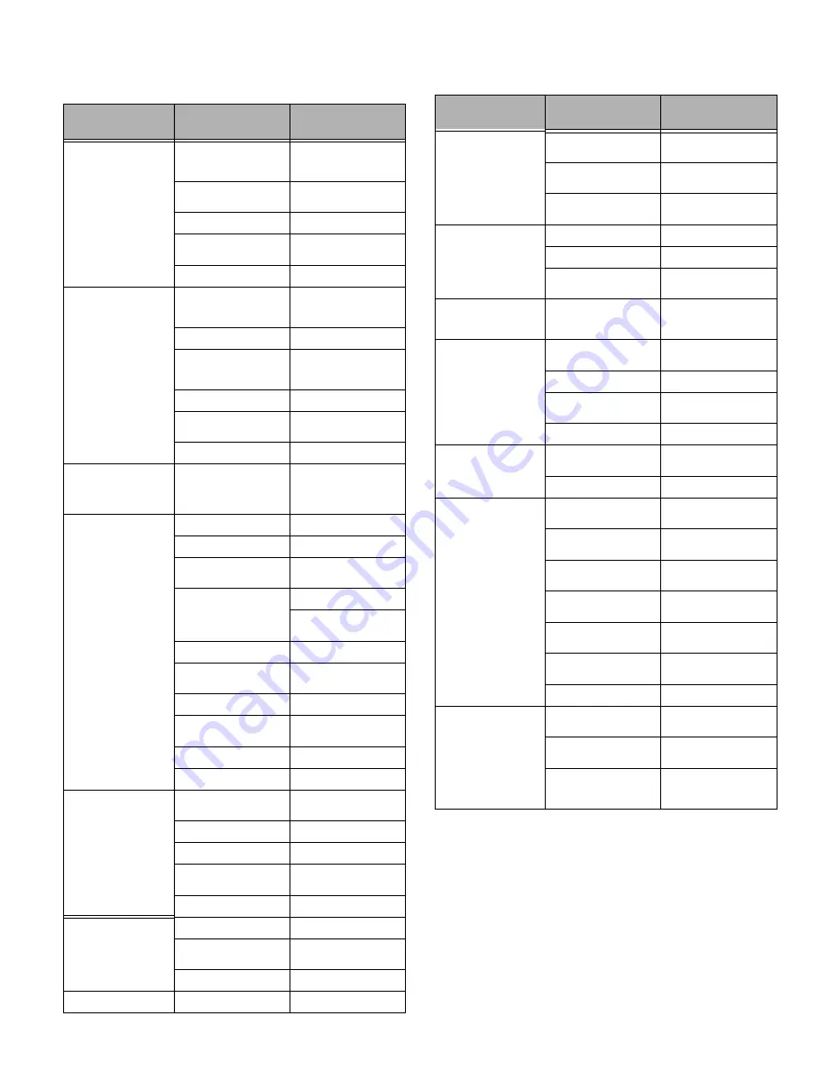
HUSTLER Super Z Diesel General Service Manual Download Page 63

115164

9-1

REV D

TROUBLESHOOTING

SYMPTOMS

PROBABLE CAUSES

SUGGESTED

REMEDIES

Starting motor does not 

crank

Steering control levers not 

in park brake position or 

switch not adjusted

Place steering control 

levers in park brake posi-

tion or re-adjust switch

Deck clutch switch 

engaged

Disengage clutch switch

Weak or dead battery

Recharge or replace

Electrical connections are 

corroded or loose

Check the electrical con-

nections

For additional causes

See engine manual

The engine will not start, 

starts hard or fails to 

keep running

No fuel or line plugged

Fill tank or replace line 

(See Fuel System section 

for more details)

Fuel valve is turned off

Open the fuel valve

There is incorrect fuel in 

the fuel system

Drain the tank and replace 

the fuel with the proper 

type

There is dirt in the fuel filter

Replace the fuel filter

Dirt, water or stale fuel in 

the fuel system

Contact your dealer

Numerous

See engine manual

Engine:

Runs with continuous 

misfiring or engine runs 

unevenly or erratically

Numerous

See engine manual

Loss of power or system 

will not operate in either 

direction

Restrictions in air cleaner

Service air cleaner

Hydraulic line blockage

See your dealer

Internal interference or 

leakage in wheel motor

See your dealer

Insufficient hydraulic oil 

supply

Check level in reservoir

Have dealer check hydrau-

lic pump

Poor compression

See your dealer

Steering linkage needs 

adjustment

Adjust linkage

Tow valve open

Close tow valve

The traction drive belt is 

worn, loose or broken

Install a new traction drive 

belt

Air in system

Check filter and fittings

For additional causes

See engine manual

Liquid cooled or Diesel 

engines overheating:

Temperature light glows

Frequent refilling of radia-

tor required

Coolant appears rusty

Audible alarm

Leaks in system

Replace/tighten hoses and 

connections

Coolant level low

Add coolant

Radiator screen clogged

Clean screen

Thermostat stickling or 

inoperative

See engine manual

Heat light malfunction

Contact your dealer

Low engine oil pressure

Low oil level

Add oil

Oil diluted or too light

Change oil and check for 

source of contamination

Failed oil pump

Contact your dealer

High oil consumption

Numerous

Contact your dealer

Mower jerky when start-

ing or operates in one 

direction only

Steering control linkage 

needs adjustment

Adjust linkage

Pump or wheel motors 

faulty

Contact your dealer

Tow valves not closed 

completely

Close tow valves

Hydraulic system oper-

ates hot (oil in reservoir 

smells rancid)

Low hydraulic oil level

Fill reservoir

Hydraulic pump faulty

Contact your dealer

Hydraulic oil heat 

exchanger clogged

Clean oil heat exchanger 

core

Mower creeps when 

steering control levers are 

in neutral

Steering linkage needs 

adjustment

Adjust linkage

Mower circles or veers in 

one direction

Steering linkage needs 

adjustment

Adjust linkage

Wheel motors faulty

Contact your dealer

Tires improperly inflated

Adjust air pressure to 8 - 12 

psi (55 - 83 KPa)

Hydraulic pump faulty

Contact your dealer

Mower creeps when park-

ing brake engaged

Steering linkage out of 

adjustment

Adjust steering linkage

Brakes need adjustment

Adjust parking brakes

There is abnormal vibra-

tion

The engine mounting bolts 

are loose

Tighten the engine mount-

ing bolts

The engine pulley, idler pul-

ley or blade pulley is loose

Tighten the appropriate 

pulley

The engine pulley is dam-

aged

Contact your dealer

The cutting blade(s) is/are 

bent or unbalanced

Install new cutting blade(s)

A blade mounting bolt is 

loose

Tighten the blade mount-

ing bolt

Spindle bearing is worn or 

loose

Replace or tighten spindle 

bearing

A blade spindle is bent

Contact your dealer

Blades do not rotate

The deck drive belt is worn, 

loose or broken

Install a new deck drive 

belt

The deck drive belt is off 

the pulley

Install the deck drive belt 

and check for a reason

Electric clutch is not 

engaging

Check and/or replace 10 

amp fuse.

Contact your dealer

SYMPTOMS

PROBABLE CAUSES

SUGGESTED

REMEDIES

Summary of Contents for Super Z Diesel

Page 1: ...115164 REV D Hustler Z Diesel General Service Manual 200 South Ridge Road Hesston Kansas 67062...

Page 2: ...t may create sparks that can start fires around dry vegetation California Public Resources Code Section 4442 6 provides that it is unlawful to use or operate an internal combustion engine on any fores...

Page 3: ...enance Precautions 2 3 Torque 3 1 Standard Torques 3 1 Special Torques 3 1 Power Unit Maintenance 4 1 Steering Adjustments 4 1 Park Brake Adjustment 4 5 Park Brake Spring Adjustment 4 6 Belts 4 6 Hydr...

Page 4: ...REV D toc 2 115164 Deck Adjustments 6 1 Deck Leveling 6 1 Blades 6 4 Belts 6 5 Deck Belt Adjustment 6 5 Deck Belt Routing Tensioning 6 9 Electrical 7 1 Troubleshooting 9 1...

Page 5: ...y as possible is the best insurance Clear away heavy build up of grease oil and dirt especially in the engine compartment and under the seat platform areas minute dust particles are abrasive to close...

Page 6: ...REV D 1 2 115164...

Page 7: ...k and store machine away from open flame or spark or pilot light such as on a water heater or appliances Refuel outdoors Never refuel or drain the gasoline from the machine indoors Never attempt to st...

Page 8: ...ion on safe machine operation Always maintain a safe distance from people and pets when mowing Always be aware of what is behind the machine before backing up Never leave machine unattended with ignit...

Page 9: ...nguishers are located and how to use them Provide adequate ventilation when charging batteries Do not smoke near battery Never check fuel level with an open flame Never use an open flame to look for l...

Page 10: ...e positive red battery cable s before connecting the negative black cable s Avoid Acid Burns Sulfuric acid in battery electrolyte is poisonous It is strong enough to burn skin eat holes in clothing an...

Page 11: ...6 M3 12 IN LBS 1 3 250 98 4 IN LBS 11 1 M4 26 4 IN LBS 3 312 204 IN LBS 23 M5 54 IN LBS 6 1 375 30 40 M6 92 4 IN LBS 10 4 438 48 65 M8 222 IN LBS 25 500 73 99 M10 37 50 562 105 143 M12 64 87 625 145...

Page 12: ...REV D 3 2 115164...

Page 13: ...rd loosen the jam nuts on the pump linkage rods and rotate the rod to lengthen the steering control linkage until the wheel s come to a stop Figure 4 3 Figure 4 4 7 Repeat for the opposite side if nec...

Page 14: ...he stops may be adjusted to help drive straight when the steering control levers are pushed forward against the stops Steering control lever in neutral position A Steering control lever B Park brake s...

Page 15: ...turn the stop set screw inward to stop the steering control lever sooner Tighten the lock nut on the stop and test again 3 Repeat this procedure until unit drives straight NOTE Since this is a hydros...

Page 16: ...perator comfort 1 By loosening the cap screws that attach the upper control lever to the lower lever the upper control lever can be pivoted to fit the operator s personal preference Figure 4 10 2 The...

Page 17: ...kes should not be engaged 8 Rotate the tire If the brake is adjusted properly the tire will still rotate but friction will start to become noticeable here However if no brake resistance is noticed the...

Page 18: ...k brake spring It should be compressed to 1 625 41 275mm If it is not adjust the nylock nut until the proper spring compression is achieved Figure 4 16 4 Repeat for the other side Belts Inspect belts...

Page 19: ...20W50 motor oil 15W50 synthetic oil or 20W50 synthetic oil when replacing the oil after an oil and filter change Do not overfill the reservoir Initial system oil and filter change must be after the f...

Page 20: ...icle s high pressure system lines Failure to perform this properly could result in bodily injury Testing Procedures 1 Use approved jack stands to raise the drive wheels off the floor A Hydraulic reser...

Page 21: ...re range 160 210 F 71 1 98 9 C 5 Increase the throttle until the flow meter reads 12 gpm 15 gpm 45 43 l min 56 78 l min Leave the throttle set in this position CAUTION Damage to the flow meter and or...

Page 22: ...lutch follow the procedure outlined below NOTE Before proceeding the clutch must be installed on the engine crankshaft and the retaining bolt torqued to 45 48 ft lbs 61 65 N m 300 psi 21 bar reading 9...

Page 23: ...d remove shim do not discard shim until proper clutch function has been confirmed Figure 4 25 3 Using a pneumatic line blow out any debris from under the brake pole and around the aluminum spacers Fig...

Page 24: ...d with the PTO switch off and clutch de energized Engage and disengage the PTO switch to ensure the proper function of the clutch 2 If clutch still does not engage then follow the troubleshooting proc...

Page 25: ...ve the dust caps and bushings from the wheel housing Retain these parts Figure 4 29 5 Remove and discard the seals Figure 4 29 6 Remove and discard the tapered roller bearings and outer bearing races...

Page 26: ...wheel housing Figure 4 32 7 Slide the wheel assembly between the caster fork legs and assemble to the fork using the axle bolt flat washers and lock nut Figure 4 33 NOTE Make sure the head of the axle...

Page 27: ...ANT When removing the oil filter take precautions to minimize oil spillage on the exhaust system The oil filter and oil drain plug are located on the underneath side of the engine Figure 5 1 Engine Ai...

Page 28: ...he condition of the filter after servicing is completely out of the filter manufacturer s control Therefore on a dust ingested engine failure there will be no warranty consideration if the air filter...

Page 29: ...Continuity test 22 Pressure sensor malfunction Yes Goes into power cutback mode Limp home mode immediately after power distribution Replace with new parts Disconnection of pressure sensor connector Ch...

Page 30: ...mode Limp home mode immediately after power distribution Replace with new parts Disconnection of pressure sensor connector Check connection Disconnection of pressure sensor harness Continuity test 33...

Page 31: ...se 2 Combination of 2 errors if 2 occur at the same time Code 31 Light up 3 times Flashing 1 time Code 04 Flashing 4 times 1 sec 1 sec 1 sec FLS 0 5 sec 0 5 sec 0 5 sec 1 CYCLE 1 CYCLE rEPEAT 1 sec 1...

Page 32: ...computer with APECS 4800 software loaded on it is required to connect to the diesel engine in order to perform ECU diagnostics using the Hustler Z Diesel Tier 4 Communication Kit Be sure to close all...

Page 33: ...the engine is running but it is not nec essary to start the engine to access any stored codes or sensor faults 8 Click Connect at the top of the APECS tool and confirm the selection of the USB cable n...

Page 34: ...REV D 5 8 115164 Figure 5 12 Figure 5 13 Figure 5 14 Figure 5 15...

Page 35: ...ttings The high idle speeds with no load should be set as follows NOTE Model numbers may or may not end with an extension after the number There are several different extensions that may be shown i e...

Page 36: ...REV D 5 10 115164...

Page 37: ...acked 2 x 4 blocks and one 1 x 4 can be used to create a 3 75 95 3mm high support at the front of the deck as shown Place two 3 high deck support blocks two stacked 2 x 4 blocks can be used to create...

Page 38: ...9 Set the amount of threads protruding on the deck lift rod from the lift block at approximately 1 25 4mm left right side Figure 6 8 10 Jam both nuts against the block 60 72 Rear Discharge Decks Sing...

Page 39: ...he front of the deck on that side to check move the blocks back and forth they should move with a slight drag Figure 6 9 17 Tighten the adjuster bolt jam nut to prevent the adjuster bolt from moving F...

Page 40: ...ll tear rather than cut the grass leaving a brown ragged top on the grass within a few hours A dull blade also requires more power from the engine Replace any blade which is bent cracked or broken Sha...

Page 41: ...ect the belt pulley grooves and flanges for wear A new belt or one in good condition should never run against the bottom of the groove Replace the pulley when this is the case otherwise the belt will...

Page 42: ...compensate for a badly worn belt or pulley 60 72 Rear Discharge Decks Single Belt System The spindle belt tension remains constant by means of a tension idler and spring The spring tension should be s...

Page 43: ...the 3 4 nut until the spring compresses to a measured length of 1 80 45 7mm 6 Re tighten the 5 8 cap screw in the front idler pulley 7 Run the belt in by starting the mower and engaging the deck Run i...

Page 44: ...r pulley C 5 8 cap screw D Belt E Pulley sled F 3 4 Jam nuts Figure 6 20 A C B 1 80 45 7mm D E C 60 Rear Discharge Decks A Idler spring B Spring chain C Spring chain anchor point Figure 6 21 72 Rear D...

Page 45: ...harge Deck NOTE The following notes are the same for the three different decks shown 1 Spring length after tensioning new belt Measured from outside of hook to outside of hook with deck set at 3 50 88...

Page 46: ...164 XR7 60 Side Discharge Deck 1 Spring length after tensioning new belt Measured from outside of hook to outside of hook with deck set at 3 50 88 9mm cut height 2 Route belt as shown Figure 6 24 9 3...

Page 47: ...NOTE The following notes are the same for the four different decks shown 1 Spring length after tensioning new belt Measured from outside of hook to outside of hook with deck set at 3 76 2mm cut height...

Page 48: ...stem NOTE The following notes are the same for the two different decks shown 1 Spring length after tensioning new belt Measured from outside of hook to outside of hook with deck set at 3 82 6mm cut he...

Page 49: ...yle NOTE The following notes are the same for the two different decks shown 1 Spring length after tensioning new belt Measured from outside of hook to outside of hook with deck set at 3 82 6mm cut hei...

Page 50: ...e Deck Two Belt System Later Style 1 Spring length after tensioning new belt Measured from outside of hook to outside of hook with deck set at 3 82 6mm cut height 2 Route belt as shown Figure 6 28 9 3...

Page 51: ...e Deck Two Belt System Later Style 1 Spring length after tensioning new belt Measured from outside of hook to outside of hook with deck set at 3 82 6mm cut height 2 Route belt as shown Figure 6 29 9 3...

Page 52: ...REV D 6 16 115164...

Page 53: ...115164 7 1 REV D ELECTRICAL Electrical Schematic Shibaura Diesel Mowers built prior to serial number 0902000 Figure 7 1...

Page 54: ...REV D 7 2 115164 Electrical Schematic Shibaura Diesel Mowers built between serial number 0902000 and serial number 1110 first four digits Figure 7 2...

Page 55: ...EV D Electrical Schematic Shibaura Diesel Domestic mowers built between serial number 1110 first four digits and serial number 13110000 Export CE mowers built after serial number 1110 first four digit...

Page 56: ...REV D 7 4 115164 Electrical Schematic Shibaura Diesel Domestic mowers built after serial number 13110000 Figure 7 4...

Page 57: ...115164 7 5 REV D Electrical Schematic Shibaura Diesel Domestic mowers built after serial number 1311000 Figure 7 5...

Page 58: ...REV D 7 6 115164...

Page 59: ...elt tension and condition 6 Check fuel system 7 Check hydraulic lines Check fuel valve 7 Check fuel tank grommets 7 Tighten lug nuts on wheels 2 Change fuel filter 7 Clean or replace hydraulic fill ca...

Page 60: ...lt every 100 hours and replace if worn or cracking is noticed Check spring tension adjustment Otherwise replace belt every 400 hours or 2 years whichever comes first Check and adjust spring tension af...

Page 61: ...Oil Reservoir 8 Hydraulic Oil Filter 9 Gauge Wheel Bearing Zerks 2 10 Engine Oil Filter 11 Deck Height Pivot Zerks 4 12 Park Brake Switch 13 Drive Tire 14 Pump Idler Zerk 1 15 Pump Belt 16 Deck Drive...

Page 62: ...4 115164 Side Discharge Deck Figure 8 5 Rear Discharge Deck Figure 8 6 Figure 8 7 1 Deck Pusher Arm Zerks 2 2 Deck Belt 1 or 2 3 Spindle Housing Zerks 3 4 Blades 3 1 2 1 4 3 4 3 3 4 1 4 3 4 3 3 4 2 1...

Page 63: ...clogged Clean screen Thermostat stickling or inoperative See engine manual Heat light malfunction Contact your dealer Low engine oil pressure Low oil level Add oil Oil diluted or too light Change oil...

Page 64: ...rvice Manual An anti scalp wheel is not set correctly Adjust the height of the anti scalp wheel The underside of the deck is dirty Clean the underside of the deck Tires improperly inflated Adjust air...

Page 65: ...ocedures 4 8 Maintenance introduction 1 1 Maintenance Locator Chart 8 3 Maintenance Precautions 2 3 Maintenance Schedule 8 1 Mower Blade Maintenance 6 4 Mower Blade Removal 6 5 Operate Machine Safely...

Reviews: