


34
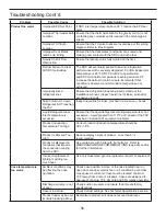
Fault Codes
A419 Fault Code/Alarm
Definition
System Status
Solution
SF flashing with OP
Open Temp sensor or sensor
wiring
Output functions according
to the selected sensor failure
mode (SF setting)
See Troubleshooting
section of A419 Elec.
Temp Cont. Install
Manual P/N: 24-7664-
1539 Rev D.
Cycle Power to reset
the control.
SF flashing with SH
Shorted temperature
sensor or sensor wiring
Output functions
according to the
selected sensor failure
mode (SF setting)
See Troubleshooting
section of A419 Elec.
Temp Cont. Install
Manual P/N: 24-7664-
1539 Rev D.
Cycle Power to reset
the control.
EE
Program failure
Output is off
Reset the control by
pressing MENU. If
problem persists,
replace the control.
Penn by Johnson Controls: A419 Series Electronic Temperature Control
A419 Display Symbols, Control Function, Ranges, Units, Values, and Factory Settings Display Symbol
Display Symbol
Control Function
Range – Units/Value
Hussmann Set Value†
SP
Setpoint*
-30 to 212 – °F (-34 to 100 –
°C)
Gravity Coil Dis. Air = 35°F
(**32°F)
Deck Coil = 30°F (**25°F)
**Shelf Coil = **26°F (Optional)
dIF
Differential*
1 to 30 – (F° or C° in 1-degree
increments
Gravity Coil Dis. Air = 1°F
Deck Coil = 1°F
**Shelf Coil = 1°F (Optional)
ASd
Anti-short Cycle Delay
0 to 12 – (in 1-minute
increments)
Gravity Coil Dis. Air = 1 min
Deck Coil = 1 min
**Shelf Coil = 1 min (Optional)
OFS
Temperature Offset
0 to 50 (F° or C° in 1-degree
increments)
0
SF
Sensor Failure Operation
(No range)— 0 = output relay
deenergized 1 = output relay
energized
1
BIN
Temperature Offset
Indicator
(No range) – BIN is displayed
and the A419 control operates
on the secondary setpoints
when the circuit between the
BIN and
COM terminals is closed.
N/A
or
Cooling or Heating Mode of
Operation
(No range) – (Cooling Mode) is
displayed when the Jump1
jumper is removed. (Heating
Mode) is displayed when the
Jump1 jumper is installed.
Cooling Mode
* The sum of the Setpoint and Differential values must be within the Setpoint range, or the control may not function properly. Also, dIF
(Differential) applies below the SP, and not a ± value (i.e. . SP - dIF = Cutout Value) † Hussmann Set Values are recommended, but
each Operational Environment may dictate minor adjustments. Increases or decreases in SP are recommended only in 1 degree Incre-
ments and assumes the specified (see Spec Sheet) Evaporator Temperature when all Suction Stop Control Solenoids are energized
(open/under load, with A419 Status Indicator(s) LED on). Refer to I/O Manual and/or Pipe Diagram for Sensor Locations. Should Set Pt
values not be achievable, verify TEV Superheat adjustments are between 2-4°F for Deck Coil and 2-6°F for Gravity Coil (with prefer-
ence at the lower end of the range) and actual Evaporator Temperature is 0/-2°F tolerance from Spec. **With Refrigerated Shelf
(Optional)


