Hussmann austral DD DELI-1 Series Installation Manual Download Page 36

PRODUCT INSTALLATION MANUAL


DD13 2T SERVICE DELI 


_________________________________________________________________________________________________________________________                                                                                                                                                                                                                                                      
Page 35


                                                                                                              Hussmann


Appendix 7 Electronic Expansion valve specification 


Hussmann use electronic expansion valve for DD Eversion series. The Electronic expansion valve specification are list in 
Table (3) 
 

Refrigerant Compatibility  

R404, R507, R134A, R407F 

Maximum Operating Pressure 

CE approval: 60 barg: 60 bar (870psi). UL approval: 45bar (652 psi) 

Refrigerant temperature 

-40T70

o

Room Temperature 

-30T70

o

Phase Current 

450mA 

Drive frequency 

50Hz-150Hz 

Phase resistance(25

 o

C) 

36ohm+-10% 

IP Rating 

IP65 

Step angle 

15

o


Linear advance 

0.03mm(0.0012inches) 

Connection 

4 wires AWG(18/22) 

Complete closing steps 

500 

Control Steps 

480 


Table (4) Specification for EEV 


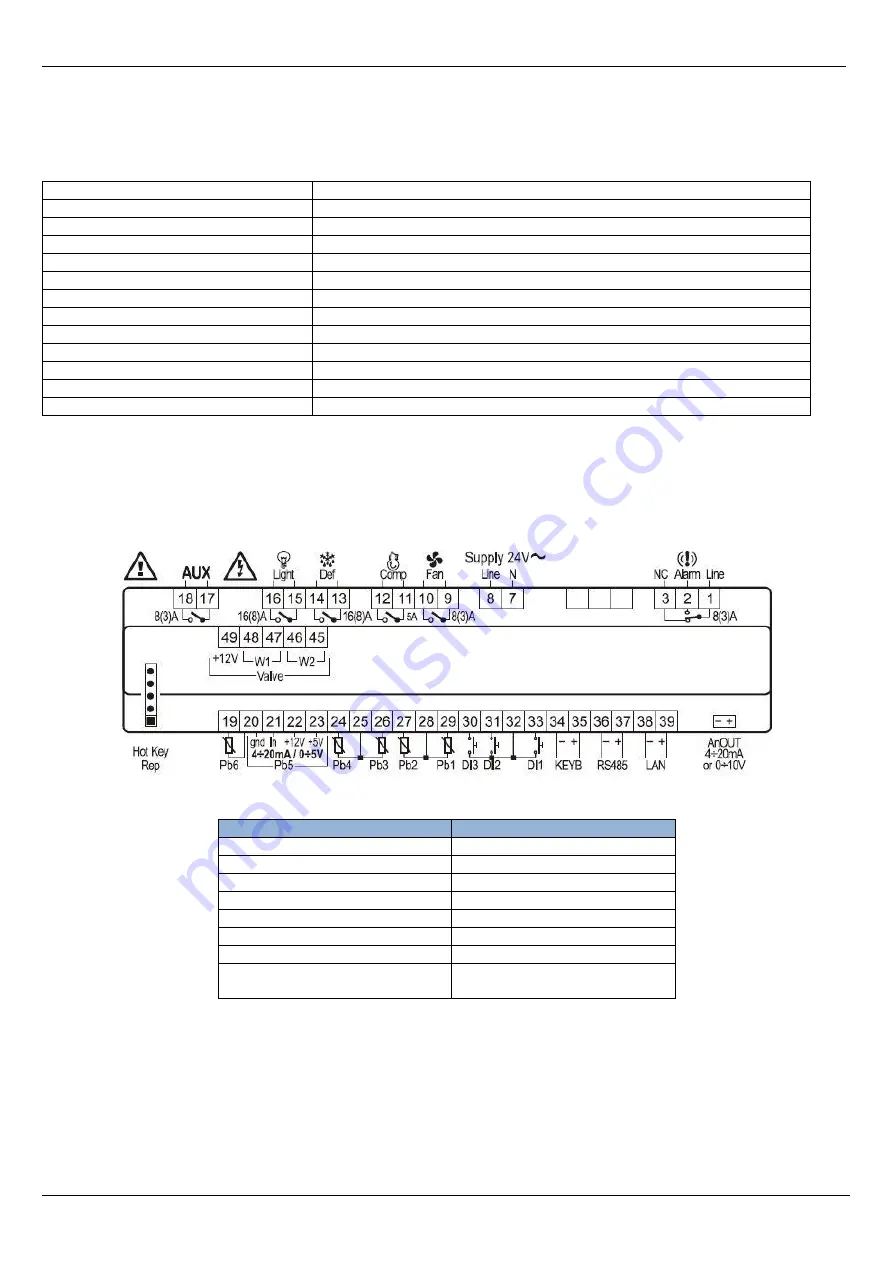
Appendix 8 Controller  


Dixell XM678D controller from Emerson are used for all DD series. 


FEATURES 

DESCRIPTION 

Temperature range 

Medium 

– Low  

Max no. of parallel connections 

No. of Relay outputs 

Expansion valve 

EEV 

Max no. of analogue inputs 

Max no. of digital inputs 

Program tool 

Hotkey (X-REP compatible) 

Serial output  

RS485 (ModBUs Compatible) 
RTC (Optional) 


Summary of Contents for austral DD DELI-1 Series

Page 1: ...DD DELI 1 SERIES SERVICED DELI INSTALLATION MANUAL IM 012 Standard remote versions The following models are covered by this Manual DD13 66 Glendenning Road Glendenning NSW 2761 PO Box 42 Doonside NSW...

Page 2: ...power supply 18 Installing sensor probes 19 Mounting fixtures 20 Commissioning 21 Cleaning case 21 Starting up 21 Start up checks 21 Decommissioning 22 Disposal 22 Operation 22 Loading Merchandise 22...

Page 3: ...ement will be instructed in Pre installation section Before installing the system make sure the power source is accessible to the cases array All the power source has to be properly earthed If any pot...

Page 4: ...L DD13 2T SERVICE DELI _________________________________________________________________________________________________________________________ Page 3 Hussmann Case Services Dimensions Fig 1 Service...

Page 5: ...y management Refer page 27 Risk Analysis For MSDS sheet contact your Hussmann Representative Handling and Transporting cases MANDATORY USE OF STRAP AND EDGE PROTECTORS FOR THE TRANSPORTATION OF HUSSMA...

Page 6: ...roduct engineering data PED sheets This manual is a guide only Always refer to the latest case information available from Hussmann Customer Service Always ensure that the moving device is of a suitabl...

Page 7: ...amage 3 Any damage must be noted on the freight documentation supply by the transport company and contact a Hussmann representative within 48 hours 4 Take clear and accurate photos of damage parts wit...

Page 8: ...ng Each case has a unique identification number as follows Job no Line up no Case sequence no within line up Example 106076 42 4 identifies this case in the 4th sequence of the line 42 for the job 106...

Page 9: ...s not level determine where the highest point of the plinth is and position the case allocated to this position first 3 Adjust the case height using the adjustable feet if fitted or metal shims do NOT...

Page 10: ..._____________________________________________ Page 9 Hussmann Fig 6 Case Levelling Fig 7 Case twisting Make sure case is level Front to Back 1 5mm Side to Side 1 5mm Make sure all adjusting feet NOT j...

Page 11: ...d air leakage To seal the joins 1 Remove the shelves and racks from the end bays if necessary 2 Remove the pan decks 3 Apply a bead of sealant approximately 10mm wide ensure case seal correctly Fig 8...

Page 12: ...refer to appendix 4 attaching case ends CAUTION Do not walk or sit on cases To join the cases 1 Draw up the required case tightly against the case already in position CAUTION Case joining bolts should...

Page 13: ...con 5 Apply either black or white silicon depending on the interior colour of the case all the way along the inside join between the cases as supplied 6 Applying slight pressure run your finger along...

Page 14: ...___________________________ Page 13 Hussmann Attaching Trims 1 Attached joining trims refer figure 11 2 Ensure that the case is level from front to back and push them together 3 Place trim to back of...

Page 15: ...es and if required silicon seal to the floor once installation is complete and drains checked for water leaks Front Panel 1 Attached front panel and align with front skid rail refer figure 12 2 Push f...

Page 16: ...______________________________________________________ Page 15 Hussmann Side kickplate 1 Attached side kickplate as per drawing refer figure 14 2 Adjust slot in kickplate to suit Make sure kickplate i...

Page 17: ...n up stand The evaporator coils have been charged with dry nitrogen in the factory Fig 15 Refrigeration access holes CAUTION Do not run refrigeration lines from another compressor through a case Since...

Page 18: ...s to ensure they are free of leaks 8 Dehydrate the refrigeration system using the triple evacuation method Use a vacuum pump to 1000 microns for the first two evacuations and 500 microns on the third...

Page 19: ...is primed before starting refrigeration Connecting Power Supply only for electronically controlled versions The appliance must be installed so the power is accessible To ensure that the appliance is...

Page 20: ...s pre fitted at the factory Probe location as per Fig 17 CAUTION Refer to relevant State or Territory legislation relating to safe working heights Probe location 1 Air off probe in the ceiling panel 2...

Page 21: ...__________________________ Page 20 Hussmann Mounting fixtures Replace racks and shelves etc as necessary to store requirements Fitting racks and shelves In manners other than configured as per the pro...

Page 22: ...ng the waste drain 2 Check that all fans and lights and light RCDs if installed are working correctly 3 Check the anti sweat circuit ensuring the thermostat is set correctly If installed 4 All electri...

Page 23: ...tallation listed previously Disposal Case disposal is to be carried out by the following 1 Metal component removed and recycled 2 Remaining by commercial waste management Operation Loading Merchandise...

Page 24: ...nspection isolate case power and contact service contractor Visually inspect drain strainer and drain for any debris which could result in the drains becoming blocked with the possibility of spilling...

Page 25: ...erforations in the rear panels and the air return grille with a clean soft cloth and mild soapy water 7 Wipe over with clean dry cloth 8 Remove the base trays wash with mild soapy water and rinse 9 Re...

Page 26: ...nents including solenoid valves fans controls earth terminals and lights are sound 9 Carry out electrical safety tests including earth continuity and insulation resistance 10 Ensure that the correct f...

Page 27: ...ore operating condition A colder store may require longer defrost duration A humid store may need more frequent defrost Case shelf arrangement has been deviated significantly from original specified s...

Page 28: ...service P1 P2 P3 P4 P5 P6 Sensor break down value out of range or sensor incorrectly configured Check the sensors rating condition and replace if necessary HA Room temperature exceed the highest room...

Page 29: ...sionally need to be attached to a case on site Use this procedure when an end attaches to a single case and when it is common to two cases Ensure that correct and appropriate manual handling technique...

Page 30: ...end fits comfortably around the canopy and the top of the case is level from front to back with case roof 6 Apply grey silicone along the inside and outside joins between the case end and end frame Se...

Page 31: ...n be adjusted with by moving the neoprene washer supplied under the glass panel The neoprene washer is located under the glass mounting fasteners between the glass and the top of the case Should the f...

Page 32: ..._____________________________________________________ Page 31 Hussmann Should the front gap required to be reduced the neoprene washer will need to be fitted under the back glass fastener This will li...

Page 33: ...LATION MANUAL DD13 2T SERVICE DELI _________________________________________________________________________________________________________________________ Page 32 Hussmann Appendix 6 Front door camb...

Page 34: ...ngers may become pinched or crushed during the positioning of base trays shelves stock Staff must be trained in the correct procedures for setting up cases and ergonomic practices Slipping Drain may l...

Page 35: ..._________________________________________________ Page 34 Hussmann Electrical Potential of wire short circuit when installing screws during drilling works Electrically isolate case before work begins...

Page 36: ...pproval 45bar 652 psi Refrigerant temperature 40T70oC Room Temperature 30T70oC Phase Current 450mA Drive frequency 50Hz 150Hz Phase resistance 25 oC 36ohm 10 IP Rating IP65 Step angle 15o Linear advan...

Page 37: ..._____ Page 36 Hussmann Appendix 9 Warranty The information in this manual is for Qualified Persons Only It is NOT an Installation Guide for NON Qualified Persons To obtain warranty information or othe...

Reviews: