background image

25

SERVICE AND ADJUSTMENTS

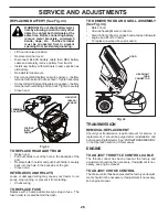
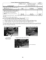
TO START ENGINE WITH A WEAK BATTERY 

(See Fig. 42) 

WARNING

:

  Lead-acid batteries gen-

 er ate ex plo sive gases.  Keep sparks, 

flame and smoking ma te ri als away from 

bat ter ies.  Always wear eye pro tec tion 

when around batteries.

If your battery is too weak to start the engine, it should be 

recharged. (See "BATTERY" in the MAINTENANCE sec-

 tion of this man u al).
If “jumper ca bles” are used for emer gen cy starting, follow 

this pro ce dure:

IMPORTANT

:  YOUR TRACTOR IS EQUIPPED WITH A 12 

VOLT SYSTEM. THE OTHER VEHICLE MUST ALSO BE A 12 

VOLT SYSTEM. DO NOT USE YOUR TRACTOR BATTERY TO 

START OTHER VEHICLES. 

TO ATTACH JUMPER CABLES -

 •  Connect one end of the RED cable to the POSITIVE 

(+) terminal of each battery(A-B), taking care not to 

short against tractor chassis.

  •  Connect one end of the BLACK ca ble to the NEGA TIVE 

(-) terminal (C) of fully charged battery.

 •  Connect the other end of the BLACK cable (D) to good 

chassis ground,  away from fuel tank and bat tery.

TO REMOVE CABLES, REVERSE ORDER -

 •  BLACK cable first from chassis and then from the fully 

charged battery.

 •  RED cable last from both batteries.

TO REMOVE WHEEL FOR REPAIRS 

(See Fig.  41)

•  Block up axle securely.
• 

Remove axle cover, retaining ring and washers to allow 

wheel removal (rear wheel contains a square key - Do 

not lose).

•  Repair tire and reassemble.
•  On rear wheels only:  align grooves in rear wheel hub 

and axle.  Insert square key.

•  Replace washers and snap retaining ring securely in 

axle groove.

•  Replace axle cover.

NOTE: 

To seal tire punctures and prevent flat tires due 

to slow leaks, tire sealant may be purchased from your 

local parts dealer. Tire sealant also prevents tire dry rot 

and corrosion.

FRONT WHEEL TOE-IN/CAM BER

Your new tractor front wheel toe-in and camber is set at the 

factory and is normal. The front wheel toe-in and camber 

are not adjustable.  If damage has occurred to affect the 

factory set front wheel toe-in or camber, contact a qualified 

service center.

Fig. 42

Fig. 41

RE TAIN ING 

RING

WASH ERS

SQUARE KEY (REAR 

WHEEL ONLY)

AXLE 

COVER

WEAK OR 

DEAD BATTERY

FULLY CHARGED

BATTERY

TO CHECK BRAKE 

If tractor requires more than five (5) feet (1,5 m) to stop at 

highest speed in high est gear on a level, dry concrete or 

paved surface, then brake must be serviced.
You may also check brake by:
1.  Park tractor on a level, dry concrete or paved surface, 

depress brake pedal all the way down and engage 

parking brake.

2.  Disengage transmission by placing freewheel control 

in “transmission disengaged” position. Pull freewheel 

control out and into the slot and release so it is held in 

the disengaged position.

The rear wheels must lock and skid when you try to manually 

push the tractor forward. If the rear wheels rotate, then the 

brake needs to be serviced. Contact a qualified service center.

Summary of Contents for YTH24V54

Page 1: ...dtheproductwarranty Estamáquinapuedeutilizargasolinaconuncontenido dehastael10 deetanol E10 Elusodeunagasolina que supere el 10 de etanol E10 anulará la garantía del producto the product warranty Please read the operator s manual carefully and make sure you understand the instructions before using the machine Por favor lea cuidadosamente y comprenda estas intrucciones antes de usar esta maquina ...

Page 2: ...he slope Keep all movement on the slopes slow and gradual Do not make sudden changes in speed or direction which could cause the machine to roll over Use extra care while operating machine with grass catch ers or other attachments they can affect the stability of the machine Do no use on steep slopes Do not try to stabilize the machine by putting your foot on the ground Do not mow near drop offs d...

Page 3: ...Use extra care when approaching blind corners shrubs trees or other objects that may block your view of a child IV TOWING Tow only with a machine that has a hitch designed for towing Do not attach towed equipment except at the hitch point Follow the manufacturer s recommendation for weight limits for towed equipment and towing on slopes Never allow children or others in or on towed equipment On sl...

Page 4: ...this manual The instructions will enable you to assemble and maintain your tractor properly Always observe the SAFETY RULES CUSTOMER RESPONSIBILITIES Read and observe the safety rules Follow a regular schedule in maintaining caring for and using your tractor Follow the instructions under Maintenance and Stor age sections of this manual Wear proper Personal Protective Equipment PPE while operating ...

Page 5: ...s r e h s a W D O 2 Rear Lift Link Assemblies 1 Front Lift Link Assembly 1 Anti Sway Bar 1 3 4 O D Washers 1 Small Retainer Springs 1 1 1 4 O D Washer 1 Wheel 1 3 8 16 Locknut 1 Shoulder Bolt Mower If Equipped 2 Keys Slope Sheet Keys 1 Oil Drain Tube Mower Front Wheel Quick Connect ...

Page 6: ...igs 3 15 1 SET PARKING BRAKE LEVER AND LOWER AT TACHMENT LIFT LEVER See Fig 2 and 3 Depress clutch brake pedal all the way down and hold Pull parking brake lever up and hold release pressure from clutch brake pedal then release parking brake lever Pedal should remain in brake position Ensure parking brake will hold tractor secure PARKING BRAKE LEVER Fig 3 CAUTION Lift lever is spring loaded Have a...

Page 7: ...rd before sliding mower under tractor Slide mower under tractor until it is centered under tractor LIFT LEVER Fig 4 H FRONT MOWER BRACKET W FRONT GAUGE WHEEL X SHOULDER BOLT Y 1 1 4 O D WASHER Z 3 8 16 LOCKNUT Fig 5 Y Z W H X Fig 7 3 TURN STEERING WHEEL LEFT AND POSITION MOWER See Fig 6 Turn steering wheel to the left as far as it will go and position mower on right side of tractor with deflector ...

Page 8: ...ion bracket F Insert other end of link E into hole in front mower bracket H and secure with washer and small retainer spring J NOTE Requires deck lifting Fig 14 FRONT LINK LOCATION E G F M E FRONT LIFT LINK ASSEMBLY F FRONT SUSPENSION BRACKET G LARGE RETAINER SPRING H FRONT MOWER BRACKET J SMALL RETAINER SPRING M ENGINE CLUTCH PULLEY J H Fig 13 7 ATTACH REAR LIFT LINKS C See Fig 13 Insert rod end ...

Page 9: ...ith fresh clean regular unleaded gasoline Become familiar with all controls their location and function Operate them before you start the engine Be sure brake system is in safe operating condition Be sure Operator Presence System and Reverse OperationSystem ROS areworkingproperly Seethe Operation and Maintenance sections in this manual It is important to purge the transmission before operating you...

Page 10: ...entify safety inform ation about hazards which can result in death serious injury and or property damage DANGER indicates a hazard which if not avoided will result in death or serious injury WARNING indicates a hazard which if not avoided could result in death or serious injury CAUTION indicates a hazard which if not avoided might result in minor or moderate injury CAUTION when used without the al...

Page 11: ...L Used for starting and controlling engine speed E ATTACHMENT CLUTCH SWITCH Used to engage the mower blades or other attachments mounted to your tractor F IGNITION SWITCH Used for starting and stopping the engine G REVERSE OPERATION SYSTEM ROS ON POSITION Allows operation of mower or other powered attachment while in reverse H LIGHT SWITCH Turns the headlights on and off J CRUISE CONTROL LEVER Use...

Page 12: ...efficiency Full speed fast offers the best mower performance ATTACHMENT CLUTCH SWITCH ENGAGED ATTACHMENT CLUTCH SWITCH DISENGAGED B C D F GROUND DRIVE To stop ground drive depress brake pedal into full BRAKE position IMPORTANT FORWARD AND REVERSE DRIVE PEDALS RETURN TO NEUTRAL POSITION WHEN NOT DEPRESSED STOPPING See Fig 18 MOWER BLADES To stop mower blades place attachment clutch control in the D...

Page 13: ...ile trimmimg or turning With forward drive pedal depressed to desired speed pull cruise control lever J up and hold while lifting your foot off the pedal then release the lever To disengage the cruise control depress the brake pedal or tap on forward drive pedal Fig 21 J L K TO ADJUST MOWER CUTTING HEIGHT See Fig 21 The position of the attachment lift lever A determines the cutting height Put atta...

Page 14: ...rvice reminder shows the total number of hours the engine has run and indicates when the engine or mower needs servicing After every 50 hours of operation the oil can icon will stay on for 2 hours or until a manual reset oc curs To reset the display manually turn the ignition switch to the on position then the off position five times 1 second on 1 second off To service engine and mower see the Mai...

Page 15: ...lizer container Run engine at least 10 minutes after adding stabilizer to allow the stabilizer to reach the carburetor Do not empty the gas tank and carburetor if using fuel stabilizer TO START ENGINE See Fig 16 When starting the engine for the first time or if the engine has run out of fuel it will take extra cranking time to move fuel from the tank to the engine Ensurefreewheelcontrolisinthetran...

Page 16: ...ntrol to half 1 2 speed Disengage parking brake 8 Drive tractor forward for approximately 5 feet 1 5 m then backwards for 5 feet 1 5 m Repeat this driving procedure three times Your transmission is now purged and now ready for normal operation MOWING TIPS DO NOT use tire chains when the mower housing is attached to tractor Mower should be properly leveled for best mowing performance See TO LEVEL M...

Page 17: ...steners Check Replace Mower Blades Che Clean Debris Off Steering Plate ck Transaxle Cooling Che Check Operator Presence ROS Systems ck V Belts Check Mower Levelness LUBRICATION CHART GENERAL RECOMMENDATIONS The warranty on this tractor does not cover items that have beensubjectedtooperatorabuseornegligence Toreceive full value from the warranty operator must maintain tractor as instructed in this ...

Page 18: ...is running with the ignition switch in the ROS ON position and the attachment clutch engaged any attempt by the operator to shift into reverse should NOT shut off the engine BLADE CARE Forbestresultsmowerbladesmustbekeptsharp Replace bent or damaged blades BATTERY Yourtractorhasabatterychargingsystemwhichissufficient for normal use However periodic charging of the battery with an automotive charge...

Page 19: ...ne with oil through oil fill dipstick tube Pour slowly Do not overfill For approximate capacity see PRODUCTSPECIFICATIONS sectionofthismanual Use gauge on oil fill cap dipstick for checking level Ensure dipstick cap is tightened securely for accurate reading Keep oil at FULL line on dipstick Tighten cap onto the tube securely when finished TEMPERATURE RANGE ANTICIPATED BEFORE NEXT OIL CHANGE SAE V...

Page 20: ...erhousingandother coolingshrouds Cleanthecoolingfinsandexternalsurfaces as necessary Ensure the cooling shrouds are reinstalled NOTE Operating the engine with a blocked grass screen dirtyorpluggedcoolingfins and orcoolingshroudsremoved will cause engine damage due to overheating CLEAN AIR SCREEN The air screen is over the air intake blower located on top of engine The air screen must be kept free ...

Page 21: ...rn the water on 6 While sitting in the operator s position on the tractor re start the engine and place the throttle lever in the Fast position IMPORTANT Recheck the area to ensure the area is clear Ensure no children are in the area while cleaning the deck 7 Move the tractor s attachment clutch control to the ENGAGED position Remainintheoperator sposition with the cutting deck engaged until the d...

Page 22: ...ct anti sway bar S from right rear mower bracket D remove retainer spring and washer and pull mower toward you until the bar falls from the hole in bracket Turn tractor steering wheel to the left as far as it will go Slide mower out from under right side of tractor TO INSTALL MOWER Follow procedure described in INSTALL MOWER AND DRIVE BELT in the Assembly section of this manual Fig 34 Fig 35 V Q P...

Page 23: ...ly checking the appearance Readjust if neces sary until you are satisfied with the results A TURN NUT LEFT TO LOWER MOWER TURN NUT RIGHT TO RAISE MOWER Fig 36 Fig 37 PRECISION SIDE TO SIDE ADJUSTMENT See Fig 37 With all tires properly inflated park tractor on level ground or driveway CAUTION Blades are sharp Protect your hands with gloves and or wrap blade with heavy cloth Raise mower to its highe...

Page 24: ...lt downward from engine pulley and around electric clutch G Slide belt toward rear of tractor off the steering plate H and remove from tractor BELT INSTALLATION Install new belt from tractor rear to front over the steer ing plate H and above clutch brake pedal shaft J Pull belt toward front of tractor and roll belt around electric clutch and onto engine pulley G Pull belt toward rear of tractor Ca...

Page 25: ...epair tire and reassemble On rear wheels only align grooves in rear wheel hub and axle Insert square key Replace washers and snap retaining ring securely in axle groove Replace axle cover NOTE To seal tire punctures and prevent flat tires due to slow leaks tire sealant may be purchased from your local parts dealer Tire sealant also prevents tire dry rot and corrosion FRONT WHEEL TOE IN CAMBER Your...

Page 26: ...tc Positive terminal must be connected first to prevent sparking from accidental grounding Lift hood to raised position Remove terminal cover Disconnect BLACK battery cable then RED battery cable and carefully remove battery from tractor Install new battery with terminals in same position as old battery Reinstall terminal cover First connect RED battery cable to positive battery terminal with bolt...

Page 27: ... Plastic cannot breathe which allows condensation to form and will cause your tractor to rust IMPORTANT NEVER COVER TRACTOR WHILE ENGINE AND EXHAUST AREAS ARE STILL WARM Immediately prepare your tractor for storage at the end of the season or if the tractor will not be used for 30 days or more WARNING Neverstorethetractorwith gasoline in the tank inside a building where fumes may reach an open fla...

Page 28: ...7 Check replace ignition switch 8 Faulty solenoid or starter 8 Check replace solenoid or starter 9 Faulty operator presence switch es 9 Contact an authorized service center department Engine clicks but will not start 1 Weak or dead battery 1 Recharge or replace battery 2 Corroded battery terminals 2 Clean battery terminals 3 Loose or damaged wiring 3 Check all wiring 4 Faulty solenoid or starter 4...

Page 29: ...place mower drive belt 9 Blades improperly installed 9 Reinstall blades sharp edge down 10 Improper blades used 10 Replace with blades listed in parts manual 11 Cloggedmowerdeckventholesfrombuildup of grass leaves trash around mandrels 11 Clean around mandrels to open vent holes Headlight s not working if so equipped 1 Switch is OFF 1 Turn switch ON 2 Bulb s or lamp s burned out 2 Replace bulb s o...

Page 30: ... never across the face Do not mow slopes greater than 15 degrees Make turns gradually to prevent tipping or loss of control Exercise extreme caution when changing direction on slopes 1 Fold this page along dotted line indicated above 2 Hold page before you so that its left edge is vertically parallel to a tree trunk or other upright structure 3 Sight across the fold in the direction of hill slope ...

Page 31: ... are not covered by this Limited Warranty In most cases these items are NOT manufactured by Husqvarna in which case they may be covered separately by their respective manufacturer s warranties if one is provided and included with the product at the time of purchase The following transmission transaxle manufacturers Dana Hydro Gear Tuff Torq provide a warranty for the transmission transaxle to the ...

Page 32: ...and or improper storage p Sprayers pumping or spraying caustic or flammable materials lack of or broken strainers or q Continued use of product after initial operational problem or failure occurs 9 Reinforced Stamped Armor Protected 10 Year Limited Fabricated Limited Lifetime Deck Warranties These Limited Warranties are for the deck shell only mechanical components parts such as belts pulleys spin...

Page 33: ... Warranty y t n a r r a W o N y t n a r r a W o N Battery 1 Year Pro rated 1 Year Pro rated No Warranty Consumer Wheeled Limited Warranty Chart 2013 Riding Lawn Tractors Product Component Residential Zero Turn Mowers RZ Only Residential Zero Turn Mowers EZ MZ M ZT Battery 1 Year Pro rated 1 Year Pro rated No Warranty y t n a r r a W o N r a e Y 1 s r a e Y 3 s t n e n o p m o C e l b a d n e p x E...

Page 34: ...on Tiller tines and Fabricated Deck shell is for the life of the product or 7 seven years after the last date of the complete unit s final production whichever comes first Deck Shell replacement will be limited to a maximum of two 2 decks within the Limited Lifetime Warranty See reference 4 b of the warranty statement RZ Two 2 Year Consumer warranty parts labor with Hydro Gear Distributor network ...

Page 35: ...u otros es combros que pueden tocar el tubo de escape partes del motor calientes y quemarse No permitir que el puente del cortacésped cargue hojas u otros residuos que pu eden causar acumulaciones Limpiar toda salpicadura de aceite o carburante antes de hacer operaciones sobre la máquina o guardarla Dejarla enfriar antes de guardarla II FUNCIONAMIENTO EN PENDIENTES Las pendientes son el mayor fact...

Page 36: ...l depósito de carburante o la abertura del contenedor durante toda la operación de abastecimiento No utilizar un dispositivo con boquilla cerrada abierta OPERACIONES DE SERVICIO GENERALES Nunca hacer funcionar la máquina en un área cerrada Mantener todas las tuercas y pernos apretados para asegu rarse de que trabaja en condiciones seguras Nunca modificar los dispositivos de seguridad Controlar su ...

Page 37: ...avordeleerydeguardarestemanual Estasinstrucciones le permitirán montar y mantener su unidad en forma adecuada Siempre observe las REGLAS DE SEGURIDAD RESPONSABILIDADES DEL CLIENTE Lea y observe las reglas de seguridad Siga un programa regular de mantenimiento cuidado y uso de su tractor Siga las instrucciones descritas en las secciones Manten imiento y Almacenamiento de este manual Utilice prendas...

Page 38: ... 1 Abrazadera pequeño de retención 1 Eslabones de levantamiento delanteros 1 3 4 Arandela 1 1 1 4 Arandela 1 Rueda 1 3 8 16 Tuerca 1 Perno Rueda Delantera De La Segadora Segadora Si Los Tiene 1 Barra Antioscilación 2 Conjunto de eslabones de levantamiento traseros 5 1 3 16 Arandela Hoja de pendiente Accesorio del conexión ...

Page 39: ...Presione el pedal de embrague freno completamente hasta abajo y manténgalo apretado Tireymantengalapalancadelfrenodeestacionamientohacia arriba libere la presión del pedal de embrague freno y luego suelte la palanca del freno de estacionamiento El pedal debe permanecer en posición de frenado Asegúrese de que el freno de estacionamiento mantendrá asegurado el tractor Fig 3 PALANCA DEL FRENO DE ESTA...

Page 40: ...ique que su trayectoria sea correcta en todos los surcos de la polea de la cortadora de césped NOTA asegúrese de que los brazos de suspensión lateral de la cortadora de césped A estén orientados hacia adelante antes de deslizar la cortadora de césped debajo del tractor Deslice la cortadora de césped debajo del tractor hasta que se encuentre centrada debajo del tractor PALANCA DE LEVANTAMIENTO Fig ...

Page 41: ...scuadra derecha de la cortadora de césped H y asegure con una arandela y un resorte de retención pequeño J NOTA Requiere levantar la plataforma Fig 13 7 INSTALE LOS ESLABONES DE LEVANTAMIENTO TRA SEROS C Vea Fig 13 Inserte el extremo de varilla del eslabón de levantamiento trasero C dentro del agujero U en el brazo de suspensión del eje de levantamiento del tractor y haga oscilar el eslabón hacia ...

Page 42: ...ucciones adecuadas para el empiezo y para purgar Vea PARA EMPEZAR EL MOTOR y PARA PURGAR LA TRANSMISIÓN en la sección de la Operación de este manual MONTAJE REVISIÓN DE LA PRESIÓN DE LAS LLANTAS Las llantas en su unidad fueron infladas demasiado en la fábrica por razones de envío La presión de las llantas correctas es im portante para obtener el mejor rendimiento en el corte Reduzca la presión de ...

Page 43: ... No seguir las siguientes instrucciones puede provocar heridas o muerte Los símbolos de aviso de seguridadse utilizan para identificar informaciones de seguridad relativas a peligros que puedenprovocar la muerte heridas graves y o daños a la máquina PELIGRO indica un peligro que si no se evita provoca muerte o lesiones graves ADVERTENCIA indica un peligro que si no se evita puede provocar muerte o...

Page 44: ...r la velocidad del motor E INTERRUPTOR DEL EMBRAGUE DEL ACCESORIO Se usa para enganchar las cuchillas segadoras o los demás accesorios montados en su tractor F INTERRUPTOR DE IGNICIÓN Se usa para hacer arrancar o hacer parar el motor G POSICIÓN ROS ON Permite la operación del conjunto segador o otro accesorio accionado mientras que en revés H INTERRUPTOR DE LUCES Enciende y apaga las luces delante...

Page 45: ...explosión del motor Gire la llave de ignición F a la posición de apagado STOP y remueva la llave al abandonar el tractor para evitar el uso no autorizado Nunca use la estrangulación para parar el motor IMPORTANTE DEJANDO EL INTERRUPTOR DE LA IGNICIÓN EN CUALQUIERPOSICIÓNOTRAQUE STOP CAUSARIQUELABATERÍA SE DESCARGUE MUERTA AVISO Bajo ciertas condiciones cuando el tractor está parado con el motor an...

Page 46: ... Vea PARA AJUSTAR LA ALTURA DE CORTE DE LA SEGADORA en la sección de Operación de este manual Conlasegadoraalaalturadeseadaparalaposicióndecorte se tienen que montar las ruedas calibradoras de modo que queden un poco sobre el suelo Instale las ruedas calibra doras en el agujero adecuado como indicados Apriete con seguridad Repita el procedimiento para el lado opuesto instalando la rueda calibrador...

Page 47: ...o al de las agujas del reloj hasta la posición ON Mire hacia abajo y hacia atrás no sólo antes de ir marcha atrás sino mientras esté yendo marcha atrás Presione lentamente el pedal reverso de la impulsión para comenzar el movimiento Cuando el uso del ROS es más necesario dé vuelta a la llave de ignición en el sentido de las agujas del reloj hasta la posición ON TRANSMISIÓN ENGANCHADA TRANSMISIÓN D...

Page 48: ...r y hágalo funcionar hasta que las tuberías de combustible y del carburador estén vacías Use combustible nuevo en la temporada siguiente Consulte las Instrucciones de Almacenamiento para obtener información adicional Nunca use productos limpiadores para motor o carburador en el tanque de combustibleporquepuedeprovocardañosirreparables Elestabilizadordecombustibleesunaalternativaacept able para min...

Page 49: ...l pedal de marchaatráshastaelfondo mantenerporcinco 5 segundos y soltar el pedal Repetir el procedimiento tres 3 veces 5 Apague el motor y embrague el freno de estacionamiento 6 Enganche la transmisión poniendo el control de rueda libre en la posición de conducir Vea PARA TRANSPORTAR en esta sección del manual 7 Sentado en el asiento del tractor empiece el motor Después que este corriendo el motor...

Page 50: ...del aceite del motor Revise la operación de los frenos Revise la presión de las llantas Verifique que el sistema de presencia del operado y ROS funcionen adecuatamente Revise si hay sujetadores sueltos TABLA DE LUBRICACIÓN 1 Cambiar más a menudo cuando se opere bajo carga pesada o en ambientes con altas temperaturas 2 Dar servicio más a menudo cuando se opere en condiciones sucias o polvorosas 3 C...

Page 51: ...tiva del operador de viajar marcha atrás NO apagará el motor 02828 POSICIÓN ROS ON MOTOR EN POSICIÓN ON OPERACIÓN NORMAL REMOCIÓN DE LA CUCHILLA Vea Fig 27 Levante la segadora a su posición más alta para permitir el acceso a las cuchillas AVISO Proteja sus manos con guantes y o envuelva la cuchilla con una tela gruesa Remueva el perno de la cuchilla dandole vueltas en el sentido inverso al de las ...

Page 52: ... está en la posición bloqueada según lo mostrado Remueva el tubo de desagüe y substituya el casquillo sobre la guarnición inferior de la válvula de desagüe Vuelva a llenar el motor con aceite a través del tubo de la varilla indicadora de nivel para relleno del aceite Vacíelo lentamente Nolollenedemasiado Paralacapacidadaproxi mada vea las Especificaciones del Producto sección de este manual Use un...

Page 53: ...fugas en la línea del combus tible y que las grapas estén colocadas en forma adecuada Inmediatamente limpie toda la gasolina derramada 00667 ABRAZADERA ABRAZADERA FILTRO DE COMBUSTIBLE FILTRO DE ACEITE DEL MOTOR Cambie el filtro de aceite del motor cada temporada o vez por medio que cambie el aceite si el tractor se usa más de 100 horas en un año NOTA Si es necesario retire las cubiertas de panel ...

Page 54: ... Fig 33 La plataforma del tractor está equipada con un puerto de lavado como parte del sistema de lavado de la plataforma Se debe utilizar después de cada uso 1 Lleve el tractor a un lugar horizontal y despejado de su césped lo bastante cerca de una boca de riego como para que llegue la manguera del jardín IMPORTANTE Asegúresedequelabocadedescargadeltractor está orientada LEJOS de su casa garaje c...

Page 55: ...fuerzalapalanca elevadora al cambiarla de posición Por el lado derecho de la cortadora desconecte la barra anti balanceo S de la barra posterior derecha de la cortadora D retire el resorte de contención y la arandela y jale la cortadora hacia usted hasta que la barra se salga del orificio de la barra Haga girar el volante del tractor todo lo posible a la izquierda Deslice la cortadora por debajo d...

Page 56: ...dora o bien hágala girar hacia la derecha para subirla Fig 36 Fig 38 Fig 39 AJUSTE DE DELANTE A ATRÁS Vea Fig 38 y 39 IMPORTANTE El piso debe quedar bien nivelado de lado a lado Para que el césped le quede perfectamente cortado las cuchil las de la cortadora deben ajustarse de tal manera que la punta anterior quede 3 1 a 12 7 mm 1 8 a 1 2 más abajo que la punta posteriorcuandolacortadoraseencuentr...

Page 57: ... del motor y alrededor del embrague eléctrico G 8 Deslice la correa hacia la parte de atrás del tractor retírela de la placa de dirección H y sáquela del tractor MONTAJE DE LA CORREA 1 Instale la correa nueva pasándola de la parte de atrás a la parte de adelante del tractor por encima de la placa de direc ción H y del vástago del pedal del embrague freno J 2 Jale la correa hacia la parte de adelan...

Page 58: ...la rueda trasera en el eje Inserte la llave cuadrada Vuelva a colocar las arandelas e inserte el anillo de retención en forma segura en la ranura del eje Vuelva a colocar la cubierta del eje AVISO Para arreglar las llantas perforadas y péra prevenir que tenga llantas pinchadas a causa de pequeñas fugas comprar de su commerciante y utilizar el sello para llantas Elsello previene que las llantas se ...

Page 59: ...or de la bombilla en forma segura hacia atrás en el agujero en la parte trasera del enrejado Cierre el capota ENTRECIERRE Y RELÉ El alambrado suelto o dañado puede producir el mal funcio namiento de su tractor o que deje de funcionar o le impida el arrancar Revise el alambrado PARA CAMBIAR EL FUSIBLE Cámbielo por un fusible tipo enchufable de 20 amps tipo auto motriz El sujetador del fusible está ...

Page 60: ...dor conectado MOTOR SISTEMA DE COMBUSTIBLE IMPORTANTE Es important evitar que se forman depositos de goma en partes fundamentales del sistema de combus tible tales como el carburador el filtro del combustible la manguera del combustiblesmezcladosconalcohol conocidocomogasohol o que tienen etanol o metanol pueden atraer humedad lo que conduce a la separación y a la formación de acudos durante elalm...

Page 61: ...fallados 8 Revise cambie el solenoide o arrancador 9 Interruptor es que exige n la presencia del operador fallado 9 Póngase en contacto con un centro de servicio cuali ficado El motor suena pero no arranca 1 Batería baja o descargada 1 Vuelva a cargar o cambie la batería 2 Terminales de la batería corroídos 2 Limpie los terminales de la batería 3 Alambrado suelto o dañado 3 Revise todo el alambrad...

Page 62: ... la cajade la segadora 8 La correa de impulsión de la segadora está des gastada o desajustada 8 Cambie ajuste la correa de impulsión de la segadora 9 Las cuchillas están mal coninstaladas 9 Vuelva a instalar las cuchillas elborde afilado hacia abajo 10 Cuchillas inadecuadas en uso 10 Cambie por las cuchillas enumeradas en este manual 11 Los agujeros de ventilación del conjunto agujeros segador tap...

Page 63: ...nunca transversalmente con respecto a las pendientes No cortar pendientes mayores de 15 grados Haga los virajes gradualmente para evitar volcarse o la pérdida de control Tenga mucho cuidado cuando cambie de dirección en las pendientes 1 Plegar esta página a lo largo de la línea punteada arriba indicada 2 Tener la página ante de sí mismos de modo que su borde izquierdo sea vertical paralelo al tron...

Page 64: ...s NO han sido fabricados por Husqvarna en cuyo caso pueden estar cubiertos por separado por la garantía de sus respectivos fabricantes si tal garantía se proporciona e incluye con el producto en el momento de la compra Los fabricantes de transmisiones transejes Dana Hydro Gear y Tuff Torq proporcionan una garantía de la transmisión transeje al comprador final o a Husqvarna Husqvarna asignará la ga...

Page 65: ...iento de los intervalos de engrase recomendados daño por agua o humedad y o almacenamiento incorrecto p Uso de pulverizadores para bombear o pulverizar materiales cáusticos o inflamables filtros ausentes o rotos o bien q Uso continuado del producto después de la aparición de un problema o falla de funcionamiento 9 Garantía limitada a 10 años de plataforma moldeada reforzada blindada y limitada de ...

Page 66: ...antía limitada de por vida Sin garantía Sin garantía a í t n a r a g n i S o d a e t a r r o r p o ñ a 1 o d a e t a r r o r p o ñ a 1 a í r e t a B a í t n a r a g n i S o ñ a 1 s o ñ a 3 s o r e d e c e r e p s e t n e n o p m o c s o r t O Motor s a í d 0 9 s a í d 0 9 s o ñ a 5 o r d a l a t e d s e j a n a r g n e e d a j a C s a í d 0 9 s a í d 0 9 s o ñ a 3 s o r e d e c e r e p s e t n e n...

Page 67: ...ipo de corte soldado es para toda la vida del producto o 7 siete años después de la última fecha de producción final de la unidad completa lo que ocurra primero La sustitución de la carcasa de corte está limitada a un máximo de dos 2 equipos de corte dentro de la Garantía limitada de por vida Consulte la referencia 4 b de la declaración de garantía RZ Dos 2 años de garantía al consumidor piezas y ...

Page 68: ...09 17 2013 BD ...

Reviews: