


9
E L E C T R IC S Y S T E M
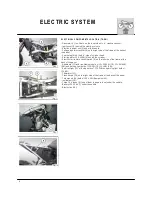
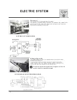
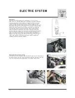
C H A R G IN G S Y S T E M C H E C K S
B a tte ry c u rre n t le a k a g e
T o g a in a cce ss to th e b a tte ry, re m o ve th e sa d d le (se e p a g e E .4 ).
R e m o ve th e B L A C K n e g a tive ca b le fro m th e b a tte ry.
M e a su re th e cu rre n t b e tw e e n th e N E G A T IV E te rm in a l o f th e b a tte ry a n d th e
N E G A T IV E ca b le
u sin g a te ste r. If th e re a d in g e xce e d 1 m A , th e re is a cu rre n t le a ka g e .
If th e ve h icle re m a in s u n u se d fo r lo n g p e rio d s (fo r m o re th a n o n e m o n th
a n d a h a lf ),it is re co m m e n d e d to re m o ve b a tte ry fro m e le ctrica l syste m a n d
sto re it in a d ry p la ce .
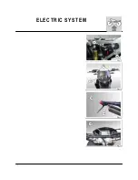
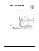
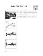
R e g u la te d vo lta g e
T o g a in a cce ss to th e b a tte ry, re m o ve th e sa d d le (se e p a g e E .4 ).
W h e n th e e n g in e is w a rm a n d w o rkin g a t slig h tly m o re th a n 3 0 0 0 rp m , m e a su re
th e te n sio n b e tw e e n th e tw o b a tte ry te rm in a ls p o sitive a n d n e g a tive w ith a te ste r
(in o rd e r to m a ke th is ch e ck th e ba tte ry m u st b e ch a rg e d ). If th e va lu e is n o t b e -
tw e e n 1 2 .5 V -1 4 .5 V , ch e ck th e g e n e ra to r a n d te n sio n - re ctifyin g re g u la to r a s d e -
scrib e d A T P A G E m .1 8 .
Summary of Contents for SM 610 2006
Page 1: ...1 W orkshop Manual SM 610 TE 610 2006 Part N 8000 A4640 04 2005 ...
Page 4: ...4 W here not otherwise specified data and instructions refer to all m odels SM 610 TE 610 ...
Page 6: ...6 ...
Page 7: ...1 GENERAL Section ...
Page 15: ...1 Section MAINTENANCE ...
Page 19: ...1 TROUBLESHOOTING Section ...
Page 25: ...1 SETTINGS AND ADJUSTMENTS Section ...
Page 41: ...1 GENERAL OPERATIONS Section ...
Page 53: ...1 ENGINE DISASSEMBLY Section ...
Page 74: ...22 ...
Page 75: ...1 ENGINE OVERHAULING Section ...
Page 100: ...26 ...
Page 101: ...1 ENGINE REASSEMBLY Section ...
Page 106: ...6 ENGINE REASSEMBLY ...
Page 110: ...10 ENGINE REASSEMBLY A 28m m 1 1 in M AIN SHAFT B 25m m 0 98 in AUXILIARY SHAFT ...
Page 129: ...1 FRONT SUSPENSION Section ...
Page 144: ...16 ...
Page 145: ...1 REAR SUSPENSION Section ...
Page 153: ...9 REAR SUSPENSION ...
Page 158: ...14 REAR SUSPENSION L 234 5 237 5 m m 9 23 9 35 in ...
Page 163: ...1 BRAKES Section ...
Page 172: ...10 ...
Page 173: ...1 ELECTRIC SYSTEM Section ...
Page 176: ...4 ELECTRIC SYSTEM ...
Page 179: ...7 ELECTRIC SYSTEM ...
Page 202: ...30 ELECTRIC SYSTEM TE SM L H COM M UTATOR ...
Page 205: ...1 ENGINE COOLING SYSTEM Section ...
Page 208: ...4 ...
Page 209: ...1 LUBRICATION CIRCUIT Section ...
Page 211: ...1 SPECIFIC TOOLS Section ...
Page 219: ...1 FRAME AND W HEELS Section ...