


12
ROTOR
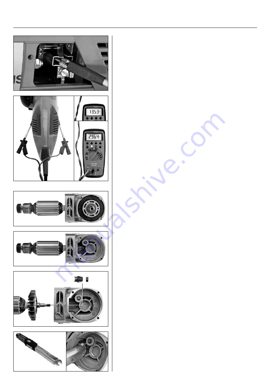
Functional test
Preparations
Remove the inspection cover to the carbon brushes.
Connect a measuring cable to each carbon brush. (You do not need to be
concerned that the stator is connected at the carbon brushes as the stator's
circuit board is broken at the circuit board and is therefore not affected by the
measurement.)
Measuring cables
Use short measuring cables and lay these close to each other: the easiest way is
to twist them. Cables run in a coiled way give incorrect readings.
Inductance measurement – Henry (H)
Inductance measurement is applied to check the condition of the rotor. The
dimension is “Henry”, abbreviated H (1H = 1000 mH). Resistance measure-
ment (ohm) produces no usable results.
Testing
Set the measuring instrument to measure mH. Turn the rotor shaft once by
turning the blade slowly ensuring you obtain the measured values for each
winding of the rotor.
Measured values
230 Volt:
Typical measured value for a correct rotor is around 13–14 mH.
120 Volt:
Typical measured value for a correct rotor is around 2.6–3.0 mH.
The inductance values may vary a lot between the measurement instruments
and machines. Pay special attention therefore to the differences in the values
during the test, rather than the absolute values. Major differences indicate a
defective rotor.
Rotor assembly
The gear housing and motor unit of both machines are designed according to
the same principle.
Four long screws link the motor unit with the gear housing. Two screws are
reached from the gear housing and two from the rear of the motor. The
screws also attach the handles to the motor housing.
In order to remove the rotor, the gear housing cover must be removed.
Both machines must have a number of components removed in order to
access the four screws that hold the cover with its crown gear.
When the drive pinion on the rotor shaft has been removed, the rotor
can then be pulled out of the gear housing. Note that the rotor shaft is left
threaded and therefore the nut must be removed in a clockwise direction.
The rotor's rear bearing is fitted with a light force fit into the motor housing.
A rubber sleeve is located between the rotor bearing and motor housing.
120 V
230 V
10
Tightening torque 33–35 Nm
When refitting, the nut must be tightened using a torque wrench at a value of
33–35 Nm. A torque wrench with a U-grip insert must be used due to the con-
fined space. The rotor shaft is left threaded and the nut is therefore tightened
in an anticlockwise direction.