background image

7 PREPARING FOR USE

24

Adjust the basic position of the hand brake lever. (

p. 85)

Adjust the basic position of the foot brake lever.

(

p. 91)

Adjust the basic position of the shift lever.

(

p. 118)

Get used to the handling characteristic of the motorcycle on suitable terrain before undertaking a more
challenging ride.

Info

This vehicle is not approved for use on public roads.
When off road, it is recommended that you are accompanied by another person on another vehicle
so that you can help each other.

Also, ride as slowly as possible and in a standing position to get a better feel for the motorcycle.

Do not undertake any off-road trips that exceed your ability and experience.

Hold the handlebar firmly with both hands and keep your feet on the footrests when riding.

(FC 450 EU, FC 450 US)

Do not carry the luggage.

(FX 450)

If luggage is carried, ensure it is fixed firmly as close as possible to the center of the vehicle and ensure
even weight distribution between the front and rear wheels.

Info

Motorcycles react sensitively to any changes of weight distribution.

Do not exceed the maximum permissible weight and maximum permissible axle loads.
Guideline

Maximum permissible overall weight

335 kg (739 lb.)

Maximum permissible front axle load

145 kg (320 lb.)

Maximum permissible rear axle load

190 kg (419 lb.)

Run in the engine. (

p. 24)

7.2

Running in the engine

During the running-in phase, do not exceed the specified engine speed and engine performance.
Guideline

Maximum engine speed

During the first operating hour

7,000 rpm

Maximum engine performance

During the first 3 operating hours

75 %

Avoid fully opening the throttle!

Summary of Contents for F2301V6

Page 1: ...OWNER S MANUAL 2022 FC 450 FX 450 Art no 3402535en ...

Page 2: ......

Page 3: ...vices designs equipment etc without prior notice and without specifying reasons to adapt these to local conditions as well as to stop production of a particular model without prior notice Husqvarna Motorcycles accepts no liability for delivery options deviations from illustrations and descriptions as well as misprints and other errors The models por trayed partly contain special equipment that doe...

Page 4: ...oot brake lever 21 6 14 Plug in stand FC 450 EU FC 450 US 21 6 15 Side stand FX 450 22 6 16 Service hour counter 22 7 PREPARING FOR USE 23 7 1 Advice on preparing for first use 23 7 2 Running in the engine 24 7 3 Starting power of lithium ion batteries at low temperatures 25 7 4 Preparing the vehicle for difficult operating conditions 25 7 5 Preparing vehicle for rides on dry sand 25 7 6 Preparing...

Page 5: ...g the air filter box cover 65 11 24 Removing the air filter 65 11 25 Installing the air filter 66 11 26 Cleaning the air filter and air filter box 66 11 27 Removing the main silencer 67 11 28 Installing the main silencer 68 11 29 Changing the glass fiber yarn filling of the main silencer 68 11 30 Removing the right side cover 69 11 31 Installing the right side cover 70 11 32 Removing the fuel tank...

Page 6: ...6 7 Checking the basic position of the shift lever 118 16 8 Adjusting the basic position of the shift lever 118 17 SERVICE WORK ON THE ENGINE 119 17 1 Changing the fuel screen 119 17 2 Checking the engine oil level 121 17 3 Changing the engine oil and oil filter cleaning the oil screens 121 17 4 Adding engine oil 124 18 CLEANING CARE 125 18 1 Cleaning the motorcycle 125 19 STORAGE 127 19 1 Storage...

Page 7: ...ally trained experts using the specialist tools required Indicates a page reference more information is provided on the specified page Indicates information with more details or tips Indicates the result of a testing step Indicates a voltage measurement Indicates a current measurement Indicates the end of an activity including potential rework 1 2 Formats used The typographical formats used in thi...

Page 8: ...ndurance competition and not primarily for use in motocross 2 2 Misuse The vehicle must only be used as intended Dangers can arise for people property and the environment through use not as intended Any use of the vehicle beyond the intended and defined use constitutes misuse Misuse also includes the use of operating and auxiliary fluids which do not meet the required specification for the respect...

Page 9: ...f noise control prior to its sale or delivery to the ultimate purchaser or while it is in use or 2 the use of the vehicle after such device or element of design has been removed or rendered inoperative by any person Among those acts presumed to constitute tampering are the acts listed below 1 Removal or puncturing of the main silencers baffles header pipes or any other components which conduct exh...

Page 10: ...e must be at a standstill models without ignition lock or remote key Special tools are necessary for certain tasks The tools are not a component of the vehicle but can be ordered using the number in parentheses Example bearing puller 15112017000 During assembly use new parts to replace parts which cannot be reused e g self locking screws and nuts expansion screws seals sealing rings O rings pins a...

Page 11: ...ke to know more about the vehicle or have questions on the material you read please contact an authorized Husqvarna Motorcycles dealer The Owner s Manual is an important component of the vehicle If the vehicle is sold the Owner s Manual must be downloaded again by the new owner The Owner s Manual can be downloaded several times using the QR code or the link on the delivery certificate The Owner s ...

Page 12: ...rrent Husqvarna Motorcycles accessories for your vehicle are available from your authorized Husqvarna Motorcycles dealer and on the Husqvarna Motorcycles website International Husqvarna Motorcycles website www husqvarna motorcycles com 3 4 Service A prerequisite for perfect operation and prevention of premature wear is that the service care and tuning work on the engine and chassis is properly car...

Page 13: ...dealer will be happy to answer any questions you may have regarding your vehicle and Husqvarna Motorcycles A list of authorized Husqvarna Motorcycles dealers can be found on the Husqvarna Motorcycles website International Husqvarna Motorcycles website www husqvarna motorcycles com ...

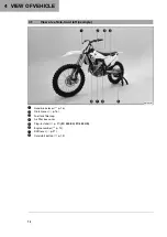
Page 14: ... vehicle front left example A01003 01 1 Hand brake lever p 16 2 Clutch lever p 16 3 Fuel tank filler cap 4 Air filter box cover 5 Plug in stand p 21 FC 450 EU FC 450 US 6 Engine number p 14 7 Shift lever p 21 8 Cold start button p 19 ...

Page 15: ... vehicle rear right example A01004 01 1 Combination switch p 17 2 Stop button p 16 3 Start button p 17 4 Throttle grip p 16 5 Fork part number p 14 6 Foot brake lever p 21 7 Level viewer engine oil 8 Level viewer for brake fluid rear ...

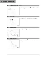
Page 16: ... on the right side of the steering head 5 2 Type label 401946 10 The type label 1 is fixed to the front of the steering head 5 3 Engine number H00940 10 The engine number 1 is stamped on the left side of the engine 5 4 Fork part number 401947 10 The fork part number 1 is stamped on the inside of the axle clamp ...

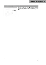
Page 17: ...SERIAL NUMBERS 5 15 5 5 Shock absorber article number 401948 10 The shock absorber article number 1 is stamped on the top of the shock absorber above the adjusting ring towards the engine side ...

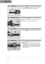
Page 18: ...gaged using the hand brake lever 6 3 Throttle grip V01558 10 The throttle grip 1 is fitted on the right side of the handlebar 6 4 Stop button S01194 10 The stop button 1 is fitted on the left side of the handlebar Possible states The stop button is in the basic position In this position the ignition circuit is closed and the engine can be started Stop button pressed In this position the ignition c...

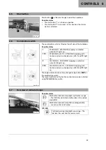
Page 19: ...and TC light up 2 ADVANCED ADVANCED mapping is activated when LED 2 lights up 2 TC ADVANCED with TC ADVANCED mapping with traction control is activated when LED 2 and TC light up The engine characteristic can be changed using button MAP on the combination switch The launch control and the traction control can also be activated using the combination switch 6 7 Overview of indicator lamps V01555 01 ...

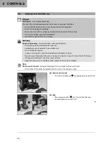
Page 20: ...contact with fuel Immediately consult a doctor if you swallow fuel Do not inhale fuel vapors In case of skin contact rinse the affected area with plenty of water Rinse the eyes thoroughly with water and consult a doctor in case of fuel contact with the eyes Change your clothing in case of fuel spills on them Keep fuels correctly in a suitable canister and out of the reach of children Note Environm...

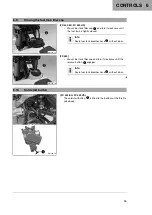
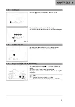
Page 21: ...nk is tightly closed Info Route fuel tank breather hose 2 without kinks V01556 10 FX 450 Mount fuel tank filler cap and turn it clockwise until the release button 1 engages Info Route fuel tank breather hose 2 without kinks 6 10 Cold start button K01109 10 FC 450 EU FC 450 US The cold start button 1 is fitted to the bottom of the throttle valve body ...

Page 22: ...ton has returned to its basic position Possible states The cold start button is activated The cold start button is pushed in all the way The cold start button is deactivated The cold start button is in its basic position 6 11 Idle speed adjusting screw K01110 10 The idle setting of the throttle valve body substantially influences the vehicle s starting behavior a stable idle speed and the vehi cle...

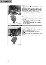
Page 23: ...oot brake lever 1 is located in front of the right footrest The foot brake lever is used to activate the rear brake 6 14 Plug in stand FC 450 EU FC 450 US H02629 10 The support for plug in stand 1 is the left side of the wheel spindle The plug in stand is used to park the motorcycle The plug in stand is used as a fork locker when transporting the motorcycle Info Remove the plug in stand before rid...

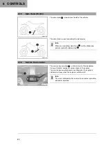
Page 24: ...1 must be folded up and secured with rubber strap 2 6 16 Service hour counter V01363 10 The service hour counter 1 is fitted in front of the handlebar It shows the total number of service hours of the engine The service hour counter begins counting when the engine is started and stops when the engine is switched off Info The value indicated by the service hour counter cannot be cleared or adjusted...

Page 25: ...ling characteristic Adapt your riding speed to the road conditions and your riding ability Warning Danger of accidents The vehicle is not designed to carry passengers Do not ride with a passenger Warning Danger of accidents The brake system fails in the event of overheating If the foot brake lever is not released the brake linings drag continuously Take your foot off the foot brake lever if you do...

Page 26: ...th hands and keep your feet on the footrests when riding FC 450 EU FC 450 US Do not carry the luggage FX 450 If luggage is carried ensure it is fixed firmly as close as possible to the center of the vehicle and ensure even weight distribution between the front and rear wheels Info Motorcycles react sensitively to any changes of weight distribution Do not exceed the maximum permissible weight and m...

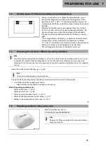
Page 27: ... the battery warms up 7 4 Preparing the vehicle for difficult operating conditions Info Use of the vehicle under difficult conditions such as on sand or on wet and muddy surfaces can result in significantly increased wear of components such as the drive train brake system or suspension components For this reason it may be necessary to inspect or replace parts before the next scheduled service Clea...

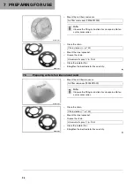
Page 28: ...versal oil spray p 146 Clean the radiator fins Straighten the bent radiator fins carefully 7 6 Preparing vehicle for rides on wet sand M01274 01 Mount the air filter rain cover Air filter rain cover 79006921000 Info Observe the fitting instructions for Husqvarna Motor cycles accessories 600868 01 Clean the chain Chain cleaner p 145 Mount the steel sprocket Grease the chain Universal oil spray p 14...

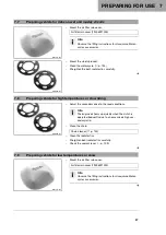
Page 29: ...ehicle for high temperatures or slow riding 600868 01 Adjust the secondary drive to the road conditions Info The engine oil heats up quickly when the clutch is operated frequently due to an excessively high sec ondary ratio Clean the chain Chain cleaner p 145 Clean the radiator fins Straighten bent radiator fins carefully Check the coolant level p 109 7 9 Preparing vehicle for low temperatures or ...

Page 30: ...e tire condition p 101 Check tire pressure p 101 Check the spoke tension p 102 Info The spoke tension must be checked regularly as incorrect spoke tension will strongly impair riding safety Clean the dust boots of the fork legs p 52 Bleed the fork legs p 52 Check the air filter Check the settings of all controls and ensure that they can be operated smoothly Check all screws nuts and hose clamps re...

Page 31: ...attempts at starting may be necessary to warm up the lithium ion battery and thereby increase the starting power During the starting process the malfunction indicator lamp lights up 8 3 Activating launch control Info The launch control helps the rider to generate optimum motorcycle acceleration at the beginning of a race The maximum speed of the engine with the throttle valve fully opened full thr...

Page 32: ...not If the engine has already been running for some time the engine must first be restarted before the launch control can be activated 8 4 Activating traction control Info The traction control reduces excessive slip on the rear wheel in favor of more control and propulsion particularly in wet conditions When traction control is switched off the rear wheel may spin more during high acceleration and...

Page 33: ...ion To shift down apply the brakes and close the throttle at the same time Pull the clutch lever and shift into a lower gear release the clutch lever slowly and either open the throttle or shift again Switch off the engine if you are likely to be running at idle speed or stationary for a long time Guideline 1 min Avoid frequent or lengthy slipping of the clutch As a result the engine oil engine an...

Page 34: ...incorrect procedure when parking Significant damage may be caused if the vehicle rolls away or falls over The components for parking the vehicle are designed only for the weight of the vehicle Park the vehicle on a firm and level surface Ensure that nobody sits on the vehicle when the vehicle is parked on a stand Note Fire hazard Hot vehicle components pose a fire hazard and explosion risk Do not ...

Page 35: ...fuel the vehicle in the vicinity of open flames or lit cigarettes Switch off the engine for refueling Make sure that no fuel is spilled particularly not on hot parts of the vehicle If any fuel is spilled wipe it off immediately Observe the specifications for refueling Warning Danger of poisoning Fuel is poisonous and a health hazard Avoid skin eye and clothing contact with fuel Immediately consult...

Page 36: ...ystem Switch off the engine Open fuel tank filler cap p 18 401522 10 Fill the fuel tank with fuel up to measurement A Guideline Measurement of A 35 mm 1 38 in Total fuel tank capacity approx FC 450 EU FC 450 US Super unleaded ROZ 95 p 144 6 8 l 1 8 US gal Total fuel tank capacity approx FX 450 Super unleaded ROZ 95 p 144 8 5 l 2 25 US gal Close the fuel tank filler cap p 19 ...

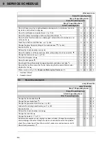
Page 37: ...brake linings p 88 Check the brake linings of the rear brake p 94 Check the brake discs p 85 Check the brake lines for damage and leakage Check the rear brake fluid level p 92 Check the free travel of the foot brake lever p 91 Check the frame p 80 Check the link fork p 80 Check the fork bearing for play Check the shock absorber heim joint for play Check the shock absorber linkage Check the tire co...

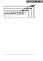
Page 38: ... fuel pressure Check the idle speed Final check Check the vehicle for operating safety and take a test ride Read out the fault memory after the test ride using the Husqvarna Motorcycles diagnostics tool Make a service entry in the Husqvarna Motorcycles Dealer net One time interval Periodic interval 9 3 Recommended work every 48 months every 12 months Every 100 operating hours Every 50 operating ho...

Page 39: ...e valves valve springs valve spring seats and valve spring retainers Change the connecting rod conrod bearing and crank pin Check the transmission and the shift mechanism Check the oil pressure control valve Change the suction pump Check the force pump and lubrication system Change the timing chain Change all engine bearings Change the radial shaft seal rings and bearing seals of the main bearing ...

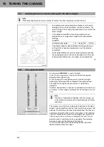
Page 40: ...k In this system suspension is located in the left fork leg and damping in the right fork leg As fork springs are no longer required a significant weight advantage is achieved when compared to conventional forks The response on slightly uneven surfaces is significantly improved In normal driving mode suspension is provided exclusively by an air cushion A steel spring is located in the left fork le...

Page 41: ...se two ranges can be adjusted separately although the transition between high speed and low speed is gradual Thus modifications in the high speed range affect the compression damping in the low speed range and vice versa 10 4 Adjusting the low speed compression damping of the shock absorber Caution Risk of injury Parts of the shock absorber will move around if the shock absorber is detached incor ...

Page 42: ...ression damping of the shock absorber Caution Risk of injury Parts of the shock absorber will move around if the shock absorber is detached incor rectly The shock absorber is filled with highly compressed nitrogen Please follow the description provided Your authorized Husqvarna Motorcycles workshop will be glad to help Info The effect of the high speed compression adjuster can be seen in the fast ...

Page 43: ...arts of the shock absorber will move around if the shock absorber is detached incor rectly The shock absorber is filled with highly compressed nitrogen Please follow the description provided Your authorized Husqvarna Motorcycles workshop will be glad to help K00468 10 Turn adjusting screw 1 clockwise up to the last perceptible click Turn counterclockwise by the number of clicks correspond ing to t...

Page 44: ... the rear wheel dimension unloaded Preparatory work Raise the motorcycle with a lift stand p 51 402415 10 Main work Position the sag gage in the rear axle and measure the distance to marking SAG on the rear fender Sag gauge 00029090500 Sag gage pin 00029990010 Note down the value as dimension A Finishing work Remove the motorcycle from the lift stand p 51 ...

Page 45: ...preload of the shock absorber p 44 10 9 Checking the riding sag of the shock absorber 402417 10 Measure dimension A of rear wheel unloaded p 42 With another person holding the motorcycle the rider wear ing full protective clothing sits on the seat in a normal sitting position feet on footrests and bounces up and down a few times The rear wheel suspension levels out Another person again measures th...

Page 46: ...oughly 402659 10 Main work Loosen screw 1 Turn adjusting ring 2 until the spring is no longer under ten sion Hook wrench 90129051000 Info If the spring cannot be fully released the spring must be removed to accurately measure the spring length Measure the total spring length while the spring is not under tension Tension the spring by turning adjusting ring 2 to specified dimension A Guideline Spri...

Page 47: ...te FC 450 US Weight of rider 65 75 kg 143 165 lb 42 N mm 240 lb in Weight of rider 75 85 kg 165 187 lb 45 N mm 257 lb in Weight of rider 85 95 kg 187 209 lb 48 N mm 274 lb in Spring rate FX 450 Weight of rider 65 75 kg 143 165 lb 42 N mm 240 lb in Weight of rider 75 85 kg 165 187 lb 45 N mm 257 lb in Weight of rider 85 95 kg 187 209 lb 48 N mm 274 lb in Info The spring rate is shown on the outside...

Page 48: ...o the suspension setting may cause a serious deterioration in the handling characteristic and overload components Only make adjustments within the recommended range Ride slowly to start with after making adjustments to get the feel of the new handling characteristic Info Check or adjust the air pressure under the same conditions at the earliest 5 minutes after switching off the engine The air susp...

Page 49: ...ure to a value outside the stated range Disconnect the fork airpump from the left fork leg When disconnecting excess pressure will escape from the hose the fork leg itself does not lose any air The fork airpump indicator switches off automatically after 80 seconds Mount the protection cap Info Only mount the protection cap by hand Finishing work Remove the motorcycle from the lift stand p 51 10 14...

Page 50: ...sion 10 15 Adjusting the rebound damping of the fork Info The hydraulic rebound damping determines the fork suspension behavior Z01370 10 Turn adjuster 1 clockwise all the way to the stop Info Adjuster 1 is located at the lower end of the right fork leg Turn counterclockwise by the number of clicks correspond ing to the fork type Guideline Rebound damping FC 450 EU Comfort 17 clicks Standard 12 cl...

Page 51: ...straightened the material becomes fatigued The handlebar may break as a result Change the handlebar if the handlebar is damaged or bent Preparatory work Remove the handlebar cushion F02595 10 Main work Remove screws 1 Take off the handlebar clamp Remove the handlebar and lay it to one side Info Cover the components to protect them against dam age Do not kink the cables and lines Remove screws 2 Ta...

Page 52: ...he handlebar clamp Mount screws 1 but do not tighten yet First bolt the handlebar clamp with screws 1 onto the longer higher side of the handlebar supports so that both parts touch Tighten screws 1 evenly Guideline Screw handlebar clamp M8 20 Nm 14 8 lbf ft Finishing work Mount the handlebar cushion ...

Page 53: ...nd raise the motorcycle at the frame underneath the engine Lift stand 81329955100 Neither wheel is in contact with the ground Secure the motorcycle against falling over 11 2 Removing the motorcycle from the lift stand Note Material damage The vehicle may be damaged by incorrect procedure when parking Significant damage may be caused if the vehicle rolls away or falls over The components for parkin...

Page 54: ...rk Tighten the bleeder screws Finishing work Remove the motorcycle from the lift stand p 51 11 4 Cleaning the dust boots of the fork legs Preparatory work Raise the motorcycle with a lift stand p 51 Remove the fork protector p 53 E00260 10 Main work Push dust boots 1 of both fork legs downward Info The dust boots remove dust and coarse dirt parti cles from the inside fork tubes Over time dirt can ...

Page 55: ...ve screws 2 and take off the left fork protector Remove screws 3 and take off the right fork protector 11 6 Installing the fork protector S01902 11 Position the fork protector on the left fork leg Mount and tighten screws 1 Guideline Remaining screws chassis M6 10 Nm 7 4 lbf ft Position the brake line and clamp Mount and tighten screws 2 Position the fork protector on the right fork leg Mount and ...

Page 56: ... legs H01182 10 Main work Position the fork legs Air bleeder screw 1 of the right fork leg is positioned to the front Valve A of the left fork leg faces the front Info Grooves are milled into the side of the upper end of the fork legs The second milled groove from the top must be flush with the upper edge of the upper triple clamp The air suspension is located in the left fork leg The pressure and...

Page 57: ...and p 51 Remove the front wheel p 97 Remove the fork legs p 53 Remove the start number plate p 59 Remove front fender p 60 Remove the handlebar cushion S02316 10 Main work Open cable holder 1 on the left and detach the wiring har ness Remove screw 2 Remove screw 3 Take off the upper triple clamp with the handlebar and place to one side Info Cover the components to protect them against dam age Do n...

Page 58: ...ctive ring 2 and O ring 3 S02318 10 Position the upper triple clamp with the handlebar Mount screw 4 but do not tighten yet H01182 11 Position the fork legs Air bleeder screw 5 of the right fork leg is positioned to the front Valve A of the left fork leg faces the front Info Grooves are milled into the side of the upper end of the fork legs The second milled groove from the top must be flush with ...

Page 59: ...hammer tap lightly on the upper triple clamp to avoid stresses Tighten screws 8 Guideline Screw top triple clamp M8 17 Nm 12 5 lbf ft Secure the wiring harness with cable holder 9 on the left Finishing work Install front fender p 60 Mount the handlebar cushion Install the start number plate p 59 Install the front wheel p 98 Check that the wiring harness throttle cables and brake and clutch lines c...

Page 60: ...y should not be detectable on the steering head bear ing If there is detectable play Adjust the steering head bearing play p 58 Move the handlebar to and fro over the entire steering range It must be possible to move the handlebar easily over the entire steering range There should be no detectable detent positions If detent positions are detected Adjust the steering head bearing play p 58 Check th...

Page 61: ...amp p 55 Install the lower triple clamp p 56 Info The steering head bearing is cleaned and lubricated in the course of removal and installation of the lower triple clamp 11 14 Removing the start number plate V01315 10 Remove screw 1 Swivel the start number plate to one side Remove screw 2 and take off the brake line guide and start number plate 11 15 Installing the start number plate V01316 10 Pos...

Page 62: ...rt number plate p 59 K01078 10 Main work Remove screws 1 and 2 Take off front fender 11 17 Installing front fender K01078 10 Main work Position front fender Mount and tighten screws 1 and 2 Guideline Remaining screws chassis M6 10 Nm 7 4 lbf ft Finishing work Install the start number plate p 59 ...

Page 63: ...ector in area A and take it off K01091 10 Remove screw 2 Remove fitting 3 Info Raise the swingarm slightly to be able to remove the screws more easily K01092 10 Press angle lever 4 toward the rear Press linkage lever 5 downward K01093 10 Remove screws 6 Pull off foot brake cylinder from the push rod S01921 01 Remove the connecting link of the chain Info Cover the components to protect them against...

Page 64: ...orber carefully at the bottom 11 19 Installing the shock absorber K01095 11 Main work Carefully position the shock absorber into the vehicle from the bottom Mount and tighten screw 1 Guideline Screw top shock absorber M10 60 Nm 44 3 lbf ft Loctite 2701 V01318 10 Position the link fork and mount the swingarm pivot Info Pay attention to flat area A Mount and tighten nut 2 Guideline Nut fork pivot M1...

Page 65: ...the angle lever and linkage lever Mount and tighten fitting 6 Guideline Nut linkage lever on angle lever M14x1 5 60 Nm 44 3 lbf ft Info Pay attention to flat area B Mount and tighten screw 7 Guideline Screw bottom shock absorber M10 60 Nm 44 3 lbf ft Loctite 2701 Info Raise the swingarm slightly to be able to mount the screw more easily V01317 11 Attach frame protector in area C and position it Mo...

Page 66: ...65 V01319 10 Main work Remove screw 1 H02218 10 Raise the rear of the seat pull the seat back and lift it off 11 21 Mounting the seat H02218 11 Main work Mount the front of the seat on the collar bushing of the fuel tank lower the seat at the rear and push the seat forward Make sure the seat is latched in place correctly V01319 10 Mount and tighten screw 1 Guideline Remaining screws chassis M6 10 ...

Page 67: ...ach catch 1 of the air filter box in area A and push forward V01320 11 Engage the air filter box cover in areas B C and D 11 24 Removing the air filter Note Engine damage Unfiltered intake air has a negative effect on the service life of the engine Dust and dirt will enter the engine without an air filter Only operate the vehicle if it is equipped with an air filter Note Environmental hazard Hazar...

Page 68: ...aining tab 2 Retaining pin 3 is secured by retaining tab 2 Info If the air filter is not mounted correctly dust and dirt may enter the engine and result in damage Finishing work Install the air filter box cover p 65 11 26 Cleaning the air filter and air filter box Note Environmental hazard Hazardous substances cause environmental damage Dispose of oils grease filters fuel cleaning agents brake flu...

Page 69: ...lter p 145 Clean the air filter box Clean the intake flange and check it for damage and tight ness Finishing work Install the air filter p 66 Install the air filter box cover p 65 11 27 Removing the main silencer Warning Danger of burns The exhaust system gets very hot when the vehicle is driven Allow the exhaust system to cool down before performing any work on the vehicle V01322 10 Detach spring...

Page 70: ...assis M6 10 Nm 7 4 lbf ft 11 29 Changing the glass fiber yarn filling of the main silencer Warning Danger of burns The exhaust system gets very hot when the vehicle is driven Allow the exhaust system to cool down before performing any work on the vehicle Info Over time the fibers of the glass fiber yarn escape and the damper burns out Not only is the noise level higher but the performance characte...

Page 71: ...nt new glass fiber yarn filling 4 on the inner tube Position new glass fiber yarn filling 3 in the silencer cap Insert O ring and silencer cap into outer tube 5 Mount and tighten all of the screws Guideline Screws on main silencer M5 7 Nm 5 2 lbf ft Finishing work Install the main silencer p 68 11 30 Removing the right side cover Preparatory work Remove the air filter box cover p 65 Remove the sea...

Page 72: ...for refueling Make sure that no fuel is spilled particularly not on hot parts of the vehicle If any fuel is spilled wipe it off immediately Observe the specifications for refueling Warning Danger of poisoning Fuel is poisonous and a health hazard Avoid skin eye and clothing contact with fuel Immediately consult a doctor if you swallow fuel Do not inhale fuel vapors In case of skin contact rinse th...

Page 73: ... Clean quick release coupling 2 thoroughly with com pressed air Info Under no circumstances should dirt enter into the fuel line Dirt in the fuel line clogs the injection valve K01089 10 Disconnect the quick release coupling Info Remaining fuel may flow out of the fuel hose Mount wash cap set A Wash cap set 81212016100 K01085 10 Remove screws 3 with the collar bushings K01086 10 Remove screw 4 wit...

Page 74: ...rcumstances should dirt enter into the fuel line Dirt in the fuel line clogs the injection valve V01353 10 Disconnect the quick release coupling Info Remaining fuel may flow out of the fuel hose Mount wash cap set A Wash cap set 81212016100 K01085 10 Remove screws 3 with the collar bushings V01354 10 Remove screw 4 with the rubber bushing K01087 10 Pull both spoilers laterally off the radiator and...

Page 75: ...void skin eye and clothing contact with fuel Immediately consult a doctor if you swallow fuel Do not inhale fuel vapors In case of skin contact rinse the affected area with plenty of water Rinse the eyes thoroughly with water and consult a doctor in case of fuel contact with the eyes Change your clothing in case of fuel spills on them Main work Check the throttle cable routing p 80 K01087 11 Posit...

Page 76: ... fuel line clogs the injection valve Spray silicone spray onto a lint free cleaning cloth and lightly lubricate the O ring of the quick release coupling Silicone spray p 146 Join quick release coupling 4 Info Route the cable and fuel line at a safe distance from the exhaust system V01354 11 FX 450 Attach the fuel tank breather hose to the fuel tank lid Mount and tighten screw 1 with the rubber bus...

Page 77: ...er p 70 Mount the seat p 64 Install the air filter box cover p 65 11 34 Checking for chain dirt accumulation 400678 01 Check the chain for coarse dirt accumulation If the chain is very dirty Clean the chain p 75 11 35 Cleaning the chain Warning Danger of accidents Lubricants on the tires reduces the road grip Remove lubricants from the tires using a suitable cleaning agent Warning Danger of accide...

Page 78: ...ansmission and rear wheel bearings wear more quickly Some components may break if overloaded If the chain is too loose the chain may fall off the engine sprocket or the rear sprocket As a result the rear wheel locks or the engine will be damaged Check the chain tension regularly Set the chain tension in accordance with the specification Preparatory work Raise the motorcycle with a lift stand p 51 ...

Page 79: ...ycle with a lift stand p 51 Check the chain tension p 76 V01325 10 Main work Loosen nut 1 Loosen nuts 2 Adjust the chain tension by turning adjusting screws 3 left and right Guideline Chain tension 55 58 mm 2 17 2 28 in Turn adjusting screws 3 on the left and right so that the markings on the left and right chain adjusters are in the same position relative to reference marks A The rear wheel is th...

Page 80: ... together 400987 10 Pull on the top section of the chain with the specified weight A Guideline Weight chain wear mea surement 10 15 kg 22 33 lb Measure distance B of 18 chain rollers in the lower chain section Info Chain wear is not always even so you should repeat this measurement at different chain positions Maximum distance B from 18 chain rollers at the longest chain section 272 mm 10 71 in If...

Page 81: ...Nm 7 4 lbf ft Loctite 243 S02331 10 Check the chain sliding piece for wear If the lower edge of the chain pins is in line with or below the chain sliding piece Change the chain sliding piece Check that the chain sliding piece is firmly seated If the chain sliding piece is loose Tighten the screw on the chain sliding piece Guideline Screw chain slid ing piece M8 15 Nm 11 1 lbf ft 402421 10 Check th...

Page 82: ...e shows signs of damage cracking or defor mation Change the frame Guideline Repairs on the frame are not permitted 11 40 Checking the link fork K01115 01 Check the link fork for damage cracking and deformation If the link fork exhibits damage cracking or deformation Change the link fork Info Always replace a damaged link fork Repair of the link fork is not authorized by Husqvarna Motorcycles 11 41...

Page 83: ...ht side cover p 70 Mount the seat p 64 Install the air filter box cover p 65 11 42 Checking the rubber grips 401197 01 Check the rubber grips on the handlebar for damage wear and looseness Info The rubber grips are vulcanized onto a sleeve on the left and onto the handle tube of the throttle grip on the right The left sleeve is clamped onto the handlebar The rubber grip can only be replaced with t...

Page 84: ...r immediately if brake fluid has been swallowed Rinse the affected area with plenty of water in the event of contact with the skin Rinse eyes thoroughly with water immediately and consult a doctor if brake fluid comes into contact with the eyes If brake fluid spills on to your clothing change the clothing Info The fluid level rises with increasing wear of the clutch facing discs Never use DOT 5 br...

Page 85: ...dous substances cause environmental damage Dispose of oils grease filters fuel cleaning agents brake fluid etc correctly and in compliance with the applicable regulations Info The fluid level rises with increasing wear of the clutch facing discs Never use DOT 5 brake fluid It is silicone based and purple in color Oil seals and clutch lines are not designed for DOT 5 brake fluid Avoid contact betwe...

Page 86: ...leeder screw 5 Only loosen bleeder screw 5 on the clutch slave cylin der until filling is possible Info Use water to immediately clean up any brake fluid that has overflowed or spilled Avoid contact between brake fluid and painted parts Brake fluid attacks paint Only use clean brake fluid from a sealed container F00166 10 Now press the fluid into the system until it emerges from hole 6 of the mast...

Page 87: ...Adjusting the basic position of the hand brake lever F00153 10 Adjust the basic position of the hand brake lever to your hand size by turning adjusting screw 1 Info Turn the adjusting screw clockwise to increase the distance between the hand brake lever and the han dlebar Turn the adjusting screw counterclockwise to decrease the distance between the hand brake lever and the handlebar The range of ...

Page 88: ...ke fluid level will cause the brake system to fail If the brake fluid level drops below the specified marking or the specified value the brake system is leaking or the brake linings are worn down Check the brake system and do not continue riding until the problem is eliminated Your authorized Husqvarna Motorcycles workshop will be glad to help Warning Danger of accidents Old brake fluid reduces th...

Page 89: ...ater in the event of contact with the skin Rinse eyes thoroughly with water immediately and consult a doctor if brake fluid comes into contact with the eyes If brake fluid spills on to your clothing change the clothing Warning Danger of accidents Old brake fluid reduces the braking effect Make sure that brake fluid for the front and rear brake is changed in accordance with the service schedule You...

Page 90: ...braking effect Ensure that worn out brake linings are replaced immediately Your authorized Husqvarna Motorcy cles workshop will be glad to help F00062 10 Check the brake linings for minimum thickness A Minimum thickness A 1 mm 0 04 in If the minimum thickness is less than specified Change the brake linings of the front brake p 88 Check the brake linings for damage and cracking If damage or wear is...

Page 91: ... on the brake discs reduces the braking effect Always keep the brake discs free of oil and grease Clean the brake discs with brake cleaner when necessary Note Environmental hazard Hazardous substances cause environmental damage Dispose of oils grease filters fuel cleaning agents brake fluid etc correctly and in compliance with the applicable regulations Info Never use DOT 5 brake fluid It is silic...

Page 92: ...inings insert pin 5 and mount cotter pins 4 Info Always change the brake linings in pairs Operate the hand brake lever repeatedly until the brake lin ings are in contact with the brake disc and there is a pressure point V01535 10 Add brake fluid up to level A Guideline Level A brake fluid level below reservoir rim 5 mm 0 2 in Brake fluid DOT 4 DOT 5 1 p 143 Position cover 2 with membrane 3 Mount a...

Page 93: ...ct spring 1 12 9 Adjusting the basic position of the foot brake lever Warning Danger of accidents The brake system fails in the event of overheating If there is no free travel on the foot brake lever pressure builds up in the brake system on the rear brake Set the free travel on the foot brake lever in accordance with the specification V01355 10 Detach spring 1 Loosen nut 4 and with push rod 5 tur...

Page 94: ...e sure that brake fluid for the front and rear brake is changed in accordance with the service schedule Your authorized Husqvarna Motorcycles workshop will be glad to help Preparatory work Check the brake linings of the rear brake p 94 V01326 10 Main work Stand the vehicle upright Check the brake fluid level in level viewer 1 If the brake fluid level has dropped below the marking A Add rear brake ...

Page 95: ...th the service schedule Your authorized Husqvarna Motorcycles workshop will be glad to help Note Environmental hazard Hazardous substances cause environmental damage Dispose of oils grease filters fuel cleaning agents brake fluid etc correctly and in compliance with the applicable regulations Info Never use DOT 5 brake fluid It is silicone based and purple in color Oil seals and brake lines are no...

Page 96: ...ch of children Wear suitable protective clothing and safety glasses Do not allow brake fluid to come into contact with the skin the eyes or clothing Consult a doctor immediately if brake fluid has been swallowed Rinse the affected area with plenty of water in the event of contact with the skin Rinse eyes thoroughly with water immediately and consult a doctor if brake fluid comes into contact with ...

Page 97: ...o Make sure that you do not press the brake caliper against the spokes when pushing back the brake pis ton Remove cotter pins 3 remove pin 4 and remove the brake linings Clean the brake caliper and the brake caliper bracket H00326 10 Check that spring plate 5 in the brake caliper and brake pad sliding plate 6 in the brake caliper bracket are seated properly Info The arrow on the spring plate point...

Page 98: ...106 10 Correct brake fluid level to marking A Brake fluid DOT 4 DOT 5 1 p 143 Mount and tighten screw cap 1 with membrane 2 and the O ring Info Use water to immediately clean up any brake fluid that has overflowed or spilled ...

Page 99: ...k the brake pis tons H02371 10 Loosen screw 1 by several rotations Loosen screws 2 Press on screw 1 to push the wheel spindle out of the axle clamp Remove screw 1 H02372 10 Warning Danger of accidents Damaged brake discs reduce the braking effect Always lay the wheel down in such a way that the brake disc is not damaged Hold the front wheel and remove the wheel spindle Take the front wheel out of ...

Page 100: ...rt the spacers Clean and grease the wheel spindle Long life grease p 145 Position the front wheel and insert the wheel spindle The brake linings are correctly positioned H02371 11 Mount and tighten screw 2 Guideline Screw front wheel spindle M20x1 5 35 Nm 25 8 lbf ft Operate the hand brake lever several times until the brake linings are seated correctly against the brake disc Remove the motorcycle...

Page 101: ...ear sprocket Info Cover the components to protect them against dam age Warning Danger of accidents Damaged brake discs reduce the braking effect Always lay the wheel down in such a way that the brake disc is not damaged Hold the rear wheel and remove the wheel spindle Take the rear wheel out of the link fork Info Do not operate the foot brake lever when the rear wheel is removed H03002 10 Remove s...

Page 102: ... Mount the chain V01325 11 Position chain adjuster 3 Mount nut 4 but do not tighten it yet Make sure that chain adjusters 3 are fitted correctly on adjusting screws 5 Check the chain tension p 76 Tighten nut 4 Guideline Nut rear wheel spin dle M25x1 5 80 Nm 59 lbf ft Info The wide adjustment range of the chain adjusters 32 mm 1 26 in enables different secondary ratios with the same chain length Ch...

Page 103: ...re age Info The tire date of manufacture is usually contained in the tire label and is indicated by the last four digits of the DOT number The first two digits indicate the week of manufacture and the last two digits the year of manufacture Husqvarna Motorcycles recommends that the tires be changed after 5 years at the latest regardless of the actual state of wear If the tires are more than 5 year...

Page 104: ...gularly and in particular on a new vehicle Your authorized Husqvarna Motorcycles workshop will be glad to help 400694 01 Strike each spoke briefly using a screwdriver blade Info The frequency of the sound depends on the spoke length and spoke diameter If spokes of the same length and diameter vibrate with a different tone this is an indication that the spoke tensions differ You should hear a high ...

Page 105: ...s materials Do not dispose of 12 V batteries as household waste Dispose of 12 V batteries at a collection point for used batteries Preparatory work Remove the air filter box cover p 65 Remove the seat p 64 S02336 10 Main work Hang the voltage regulator to the side Disconnect negative cable 1 from the 12 V battery Pull back positive terminal cover 2 and disconnect positive cable 3 from the 12 V bat...

Page 106: ...Position the voltage regulator Finishing work Mount the seat p 64 Install the air filter box cover p 65 14 3 Charging the 12 V battery Warning Risk of injury 12 V batteries contain harmful substances Keep 12 V batteries out of the reach of children Keep sparks and open flames away from 12 V batteries Only charge 12 V batteries in well ventilated rooms Maintain a minimum clearance from inflammable ...

Page 107: ...103 F01568 10 Main work Check the battery voltage Battery voltage 9 V Do not charge the 12 V battery Replace the 12 V battery and dispose of the old 12 V battery properly If the specifications have been met Battery voltage 9 V Connect a battery charger to the 12 V battery Switch on the battery charger Guideline The charging current charging voltage and charg ing time must not be exceeded Maximum c...

Page 108: ... electrical system Only use fuses with the required ampere value Do not bypass or repair fuses Caution Danger of burns The voltage regulator gets very hot when the vehicle is driven Allow the voltage regulator to cool down before performing any work Info The main fuse protects all electrical power consumers of the vehicle It is located in the starter relay housing under the seat Preparatory work R...

Page 109: ...w main fuse Fuse 58011109110 p 136 Check that the electrical system is functioning properly Tip Insert a spare fuse so that it is available if needed Mount the protection caps Mount the starter relay onto the holder and route the cable Finishing work Mount the seat p 64 Install the air filter box cover p 65 14 5 Diagnostics connector H00933 12 Diagnostics connector 1 is located under the seat ...

Page 110: ...he radiator hoses or other cooling system components if the engine or the cooling system are at operating temperature Allow the cooling system and the engine to cool down before you open the radiator the radiator hoses or other components of the cooling system In the event of scalding rinse the area affected immediately with lukewarm water Warning Danger of poisoning Coolant is toxic and a health ...

Page 111: ...ine to cool down before you open the radiator the radiator hoses or other components of the cooling system In the event of scalding rinse the area affected immediately with lukewarm water Warning Danger of poisoning Coolant is toxic and a health hazard Keep coolant out of the reach of children Do not allow coolant to come into contact with the skin the eyes and clothing Consult a doctor immediatel...

Page 112: ...y of water in the event of contact with the skin Rinse eyes thoroughly with water and consult a doctor immediately if coolant gets into the eyes Change clothing if coolant spills onto your clothing Condition The engine is cold V01333 10 Position the motorcycle upright Place an appropriate container under the water pump cover Remove screw 1 Take off radiator cap 2 Completely drain the coolant Mount...

Page 113: ...ngine to cool down before you open the radiator the radiator hoses or other components of the cooling system In the event of scalding rinse the area affected immediately with lukewarm water Warning Danger of poisoning Coolant is toxic and a health hazard Keep coolant out of the reach of children Do not allow coolant to come into contact with the skin the eyes and clothing Consult a doctor immediat...

Page 114: ...Guideline Screw water pump cover M6 10 Nm 7 4 lbf ft Pour coolant in up to level A above the radiator fins Guideline Distance A above the radi ator fins 10 mm 0 39 in Coolant 1 20 l 1 27 qt Coolant p 143 Mount the radiator cap Go for a short test ride Check the coolant level p 109 ...

Page 115: ...he throttle cable p 113 Danger Danger of poisoning Exhaust gases are toxic and inhaling them may result in unconsciousness and death Always make sure there is sufficient ventilation when running the engine Use effective exhaust extraction when starting or running the engine in an enclosed space Start the engine and let it run at idle speed Move the handle bar to and fro over the entire steering ra...

Page 116: ...e throttle grip for smooth operation V01361 10 FX 450 Move the handlebar to the straight ahead position Push back sleeve 1 Loosen nut 2 Turn adjusting screw 3 in as far as possible Loosen nut 4 Push cold start button 6 all the way to the stop Turn adjusting screw 5 so that the cold start button moves to the basic position when the throttle grip is turned to the front Tighten nut 4 Turn adjusting s...

Page 117: ... Remove guide plate 4 from handle tube 5 Position the required guide plate on the grip tube Guideline The label OUTSIDE must be visible Marking A must be positioned at marking B Grey guide plate 79002014000 Alternative 1 Black guide plate 79002014100 Info The gray guide plate opens the throttle valve more slowly The black guide plate opens the throttle valve more quickly The gray guide plate is mo...

Page 118: ...restarting The traction control can also be activated in each mapping using the TC button The mapping can also be changed during the ride H02889 01 Activating STANDARD mapping Press button MAP until LED 1 lights up Guideline Engine speed 4 000 rpm STANDARD balanced response H02886 01 Activating ADVANCED mapping Press button MAP until LED 2 lights up Guideline Engine speed 4 000 rpm ADVANCED direct...

Page 119: ...lockwise raises the idle speed 16 6 Teaching the throttle valve position Info If the control unit detects that the throttle valve position at idle speed needs to be retaught then the malfunction indicator lamp flashes 2x per second H02263 10 Danger Danger of poisoning Exhaust gases are toxic and inhaling them may result in unconsciousness and death Always make sure there is sufficient ventilation ...

Page 120: ...dge of boot 10 20 mm 0 39 0 79 in If the distance does not meet specifications Adjust the basic position of the shift lever p 118 16 8 Adjusting the basic position of the shift lever 401950 12 Remove screw 1 with the washers and take off shift lever 2 401951 10 Clean gear teeth A of the shift lever and shift shaft Mount the shift lever on the shift shaft in the required position and engage gearing...

Page 121: ...h plenty of water Rinse the eyes thoroughly with water and consult a doctor in case of fuel contact with the eyes Change your clothing in case of fuel spills on them Note Environmental hazard Improper handling of fuel is a danger to the environment Do not allow fuel to enter the groundwater the soil or the sewage system K01103 10 FC 450 EU FC 450 US Clean quick release coupling 1 thoroughly with c...

Page 122: ...ine clogs the injection valve Disconnect the quick release coupling Info Remaining fuel may flow out of the fuel hose Pull fuel screen 2 out of the connecting piece Insert the new fuel screen all the way into the connecting piece Spray silicone spray onto a lint free cleaning cloth and lightly lubricate the O ring of the quick release coupling Silicone spray p 146 Join the quick release coupling D...

Page 123: ... level is between the middle of the level viewer A and the upper edge of the level viewer B If the engine oil does not reach the middle of level viewer A Add engine oil p 124 17 3 Changing the engine oil and oil filter cleaning the oil screens Warning Danger of scalding Engine and gear oil get very hot when the motorcycle is ridden Wear suitable protective clothing and safety gloves In the event o...

Page 124: ...ng oil screen 4 and the O rings Allow the engine oil to drain completely Thoroughly clean the parts and the sealing surfaces K01069 11 Mount and tighten screw plug 2 with the short oil screen and the O rings Guideline Screw plug oil screen M20x1 5 15 Nm 11 1 lbf ft K01071 10 Position long oil screen 4 with the O rings on a pin wrench Position the pin wrench through the drill hole of the screw plug...

Page 125: ...Thoroughly clean the parts and the sealing surfaces K01073 11 Lay the motorcycle on its side and fill the oil filter housing to about full with engine oil Place the oil filter into the oil filter housing Lubricate the O ring of the oil filter cover and mount it with oil filter cover 7 Mount and tighten the screws Guideline Screw oil filter cover M6 10 Nm 7 4 lbf ft Stand the motorcycle upright 401...

Page 126: ...01955 10 Main work Remove filler plug 1 with the O ring Add the same engine oil used when the last oil change was carried out Engine oil SAE 10W 50 p 143 Info For optimal performance of the engine oil do not mix different types of engine oil Husqvarna Motorcycles recommends changing the engine oil Mount and tighten the filler plug together with the O ring Danger Danger of poisoning Exhaust gases a...

Page 127: ...ce of the motorcycle over a long period clean it regularly Avoid direct sunshine when cleaning the motorcycle 401061 01 Close off exhaust system to keep water from entering Remove loose dirt first with a soft jet of water Spray the heavily soiled parts with a normal commercial motorcycle cleaner and clean using a brush Motorcycle cleaner p 145 Info Use warm water containing normal motorcycle clean...

Page 128: ...te all moving parts and pivot points Clean the chain p 75 Treat bare metal except for brake discs and the exhaust sys tem with a corrosion inhibitor Preserving materials for paints metal and rubber p 145 Treat all plastic parts and powder coated parts with a mild cleaning and care product Special cleaner for glossy and matte paint finishes metal and plastic surfaces p 146 ...

Page 129: ... or replacements are necessary you should do this during the storage period less workshop overload In this way you can avoid long workshop waiting times at the start of the new season 401058 01 When refueling for the last time before taking the motorcycle out of service add fuel additive Fuel additive p 145 Refuel p 33 Clean the motorcycle p 125 Change the engine oil and the oil filter clean the o...

Page 130: ...ime only Since the engine cannot warm up properly the water vapor produced during combustion condenses and causes valves and exhaust system to rust 19 2 Preparing for use after storage 401059 01 Install the 12 V battery p 104 Remove the motorcycle from the lift stand p 51 Perform checks and maintenance measures when preparing for use p 28 Make a test ride ...

Page 131: ...rness visual check Check the electrical system Malfunction in the electronic fuel injection Read out the fault memory using the Husqvarna Motorcycles diagnostics tool Engine does not speed up Malfunction in the electronic fuel injection Read out the fault memory using the Husqvarna Motorcycles diagnostics tool Engine has too little power Air filter is very dirty Clean the air filter and air filter...

Page 132: ...rcycles diagnostics tool High oil consumption Engine vent hose bent Route the vent hose without bends or change it if necessary Engine oil level too high Check the engine oil level p 121 Engine oil too thin low viscos ity Change the engine oil and the oil filter clean the oil screens p 121 Piston or cylinder worn Measure the piston cylinder mounting clearance 12 V battery discharged 12 V battery i...

Page 133: ... for malfunc tion indicator lamp 12 Malfunction indicator lamp flashes 1x long 2x short Error level condition Coolant temperature sensor circuit fault Coolant temperature sensor input signal too low Blink code for malfunc tion indicator lamp 13 Malfunction indicator lamp flashes 1x long 3x short Error level condition Intake air temperature sensor circuit fault Intake air temperature sensor input s...

Page 134: ...ircuit fault Blink code for malfunc tion indicator lamp 41 Malfunction indicator lamp flashes 4x long 1x short Error level condition Fuel pump controller short circuit to ground open circuit Fuel pump controller open circuit short circuit to plus Blink code for malfunc tion indicator lamp 65 Malfunction indicator lamp flashes 6x long 5x short Error level condition EEPROM malfunction Blink code for...

Page 135: ...pin bearing FC 450 EU FC 450 US No bearing bush DLC coated piston pin Pistons Forged light alloy Piston rings 1 compression ring 1 oil scraper ring Engine lubrication Pressure circulation lubrication with 2 trochoidal pumps Primary transmission 31 76 Clutch Multidisc clutch in oil bath hydraulically activated Gearbox 5 gear transmission claw shifted Transmission ratio First gear 16 32 Second gear ...

Page 136: ... cover M5 6 Nm 4 4 lbf ft Loctite 243 Nut water pump impeller M6 6 Nm 4 4 lbf ft Loctite 243 Screw alternator cover M6 10 Nm 7 4 lbf ft Screw clutch cover M6 10 Nm 7 4 lbf ft Screw clutch slave cylinder M6 10 Nm 7 4 lbf ft Screw cylinder head M6 10 Nm 7 4 lbf ft Screw engine case M6 10 Nm 7 4 lbf ft Screw exhaust flange M6 10 Nm 7 4 lbf ft Loctite 243 Screw oil filter cover M6 10 Nm 7 4 lbf ft Scr...

Page 137: ...ge 50 Nm 36 9 lbf ft Collar and thread oiled Nut rotor M12x1 60 Nm 44 3 lbf ft Thread oiled with engine oil cone degreased Oil drain plug with magnet M12x1 5 20 Nm 14 8 lbf ft Screw plug oil pressure control valve M12x1 5 20 Nm 14 8 lbf ft Nut inner clutch hub M18x1 5 100 Nm 73 8 lbf ft Loctite 243 Nut primary gear wheel M20LHx1 5 100 Nm 73 8 lbf ft Loctite 243 Screw plug oil screen M20x1 5 15 Nm ...

Page 138: ...0 bar 15 psi rear 1 0 bar 15 psi Secondary ratio FC 450 EU FC 450 US 13 49 Secondary ratio FX 450 13 48 Chain 5 8 x 1 4 Rear sprockets available 48 49 50 51 52 Steering head angle 63 9 Wheelbase 1 485 10 mm 58 46 0 39 in Ground clearance unloaded 370 mm 14 57 in Seat height unloaded 950 mm 37 4 in Weight without fuel approx FC 450 EU FC 450 US 101 kg 223 lb Weight without fuel approx FX 450 101 3 ...

Page 139: ...dard 12 clicks Sport 7 clicks Rebound damping Comfort 17 clicks Standard 12 clicks Sport 7 clicks Air pressure 10 7 bar 155 psi Fork length 940 mm 37 01 in Oil capacity external mechanism right 230 10 50 ml 7 78 0 34 1 69 fl oz Fork oil SAE 4 48601166S1 p 144 Oil capacity external mechanism left 230 10 50 ml 7 78 0 34 1 69 fl oz Fork oil SAE 4 48601166S1 p 144 Oil capacity right cartridge 370 ml 1...

Page 140: ...icks Sport 7 clicks Rebound damping Comfort 23 clicks Standard 18 clicks Sport 13 clicks Air pressure 10 bar 145 psi Fork length 950 mm 37 4 in Oil capacity external mechanism right 230 10 50 ml 7 78 0 34 1 69 fl oz Fork oil SAE 4 48601166S1 p 144 Oil capacity external mechanism left 230 10 50 ml 7 78 0 34 1 69 fl oz Fork oil SAE 4 48601166S1 p 144 Oil capacity right cartridge 380 ml 12 85 fl oz F...

Page 141: ... SAE 2 5 50180751S1 p 144 22 8 2 FC 450 US Shock absorber article number 18 15 7U 59 Shock absorber WP XACT 5750 Lowspeed compression damping Comfort 17 clicks Standard 15 clicks Sport 13 clicks Highspeed compression damping Comfort 2 5 turns Standard 2 turns Sport 1 5 turns Rebound damping Comfort 17 clicks Standard 15 clicks Sport 13 clicks Spring preload 7 mm 0 28 in Spring rate Weight of rider...

Page 142: ...der 85 95 kg 187 209 lb 48 N mm 274 lb in Spring length 260 mm 10 24 in Gas pressure 10 bar 145 psi Static sag 35 mm 1 38 in Riding sag 105 mm 4 13 in Fitted length 477 mm 18 78 in Shock absorber oil Shock absorber fluid SAE 2 5 50180751S1 p 144 22 9 Chassis tightening torques Screw air filter box EJOT PT K70x25 5 Nm 3 7 lbf ft Screw combination switch EJOT PT K50x18 2 Nm 1 5 lbf ft Screw intake a...

Page 143: ... 10 3 lbf ft Loctite 243 Screw fuel tank spoiler on radia tor M6 6 Nm 4 4 lbf ft Screw indicator lamp bracket M6 5 Nm 3 7 lbf ft Screw rear brake disc M6 14 Nm 10 3 lbf ft Loctite 243 Screw throttle grip M6 5 Nm 3 7 lbf ft Fuel connection on fuel tank M8 15 Nm 11 1 lbf ft Nut foot brake lever stop M8 20 Nm 14 8 lbf ft Nut rear sprocket screw M8 35 Nm 25 8 lbf ft Loctite 2701 Nut rim lock M8 12 Nm ...

Page 144: ...40 Nm 29 5 lbf ft Loctite 243 Screw top shock absorber M10 60 Nm 44 3 lbf ft Loctite 2701 Nut fuel pump M12 15 Nm 11 1 lbf ft Nut angle lever to link fork M14x1 5 60 Nm 44 3 lbf ft Nut frame on linkage lever M14x1 5 60 Nm 44 3 lbf ft Nut linkage lever on angle lever M14x1 5 60 Nm 44 3 lbf ft Nut fork pivot M16x1 5 100 Nm 73 8 lbf ft Screw front wheel spindle M20x1 5 35 Nm 25 8 lbf ft Screw top ste...

Page 145: ...s Only use coolant that complies with the requirements stated see specifications on the container and that has the relevant properties Antifreeze protection to at least 25 C 13 F The mixture ratio must be adjusted to the necessary antifreeze protection Use distilled water if the coolant needs to be diluted The use of premixed coolant is recommended Observe the coolant manufacturer specifications f...

Page 146: ...on SAE p 147 SAE 2 5 Guideline Use only oils that comply with the specified standards see specifications on the container and that exhibit the corresponding properties Super unleaded ROZ 95 Standard classification DIN EN 228 ROZ 95 Guideline Only use super unleaded fuel that matches or is equivalent to the specified standard Fuel with an ethanol content of up to 10 E10 fuel is safe to use Info Do ...

Page 147: ...r High viscosity grease Recommended supplier SKF LGHB 2 Long life grease Recommended supplier MOTOREX Bike Grease 2000 Motorcycle cleaner Recommended supplier MOTOREX Moto Clean Off road chain spray Recommended supplier MOTOREX Chainlube Offroad Oil for foam air filter Recommended supplier MOTOREX Racing Bio Liquid Power Preserving materials for paints metal and rubber Recommended supplier MOTOREX...

Page 148: ...pray Special cleaner for glossy and matte paint finishes metal and plastic surfaces Recommended supplier MOTOREX Quick Cleaner Special grease 00062010053 Recommended supplier Klüber Lubrication KLÜBERFOOD NH1 34 401 Universal oil spray Recommended supplier MOTOREX Joker 440 Synthetic ...

Page 149: ...ice intervals are demanded for automobile engines the focus for motorcycle engines is on high performance at high engine speeds In most motorcycle engines the transmission and clutch are lubricated with the same oil The JASO T903 MA2 standard meets these special requirements SAE The SAE viscosity classes were defined by the Society of Automotive Engineers and are used for classifying oils accordin...

Page 150: ... 148 Launch control Vehicles electronics functions for achieving the best possible acceleration from a standing position OBD On board diagnosis Vehicle system which monitors the specified param eters of the vehicle electronics ...

Page 151: ...LIST OF ABBREVIATIONS 27 149 Art no Article number ca circa cf compare e g for example etc et cetera i a inter alia no number poss possibly ...

Page 152: ...ctive driving aids are also represented by yellow or orange symbols Malfunction indicator lamp lights up flashes orange The OBD has detected a malfunction in the vehicle electronics Malfunction indicator lamp flashes orange rapidly Launch control is activated Fuel level warning lamp lights up orange The fuel level has reached the reserve mark ...

Page 153: ...oolant 111 112 135 engine oil 123 135 Fuel 34 135 Chain checking 78 cleaning 75 Chain guide checking 78 Chain tension adjusting 77 checking 76 Characteristic map of the throttle response adjusting 115 Clutch fluid level checking correcting 82 fluid changing 83 Clutch lever 16 basic position adjusting 82 Cold start button 19 Compression damping fork adjusting 47 Coolant antifreeze and coolant level...

Page 154: ...ver 16 basic position adjusting 85 free travel checking 85 Handlebar position 49 adjusting 49 High speed compression damping shock absorber adjusting 40 I Idle speed adjusting 116 Idle speed adjusting screw 20 Implied warranty 10 Indicator lamps overview 17 Intended use 6 L Launch control activating 29 Link fork checking 80 Lower triple clamp installing 56 removing 55 Low speed compression damping...

Page 155: ...amping adjusting 41 removing 61 riding sag checking 43 spring preload adjusting 44 static sag checking 43 Shock absorber article number 15 Side stand 22 Spare parts 10 Spoke tension checking 102 Start button 17 Start number plate installing 59 removing 59 Starting 28 Starting power of lithium ion batteries at low temperatures 25 Steering head bearing lubricating 59 Steering head bearing play adjus...

Page 156: ...INDEX 154 rear right 13 W Work rules 8 ...

Page 157: ... 3402535en 3402535en 04 2021 Husqvarna Motorcycles GmbH Stallhofnerstraße 3 5230 Mattighofen Austria www husqvarna motorcycles com Photo Mitterbauer KISKA Husqvarna Motorcycles GmbH ...

Reviews: