24
2
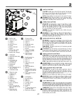
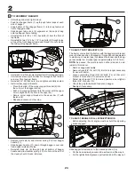
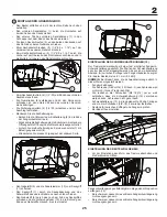
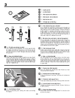
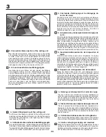
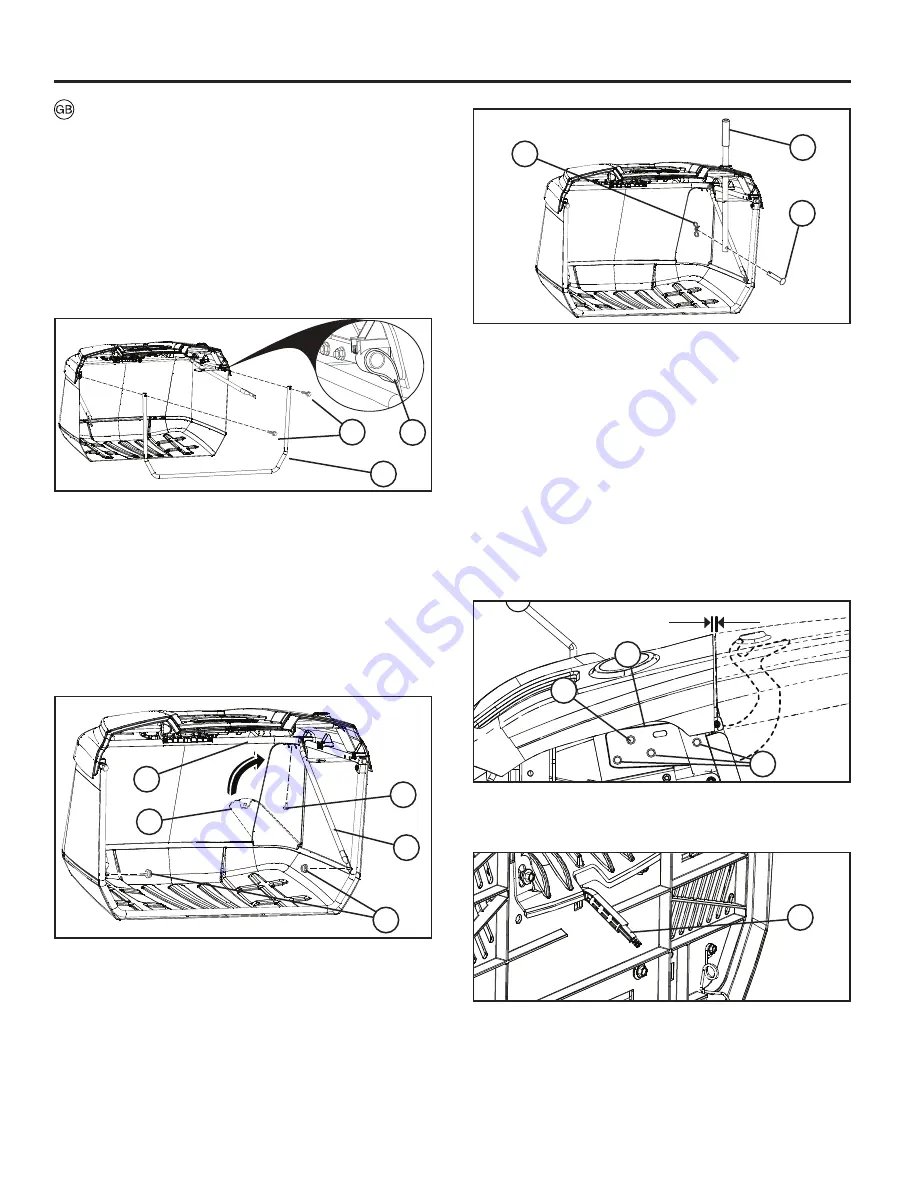
TO ASSEMBLY BAGGER
• Unfold bag and stand right side up.
• Feed front bagger frame (1) up through fabric loops at each
side of bagger.
• Snap bottom of front bagger frame (1) into snap feature at
front of bagger bottom.
• Slide bagger fabric loop (2) segments at the ends of bag
onto top bagger frame tubing.
• Uninstall two (1\4”-20 x 1.15”) hex bolts (3) from the front of
top frame.
• Reinstall the two (1\4”-20 x 1.15”) hex bolts (3) through holes
at top of the front bagger frame and thread into nuts inside
the tubing of top bagger frame.
• Uninstall (1/4”-20) lock nuts (4) at bottom of front bagger frame.
• Unfold cross braces (5) and attach to carriage bolts at bottom
corners of front bagger frame.
• Reinstall (1/4”-20) lock nuts (4) and tighten until fully seated.
• Install corner support brackets.
• Place the bottom of the corner support bracket (6) into
the corner of the bagger bottom.
• Push corner support bracket into the corner until the upper
hole is aligned with the hole in the upper bar.
• Secure corner support bracket to the upper bar (7) with
fastener (8).
• Repeat procedure on other side.
• Remove clevis pin (9) and retainer spring (10) from bagger
handle (11).
• Slide bagger handle (11) down through bagger cover and
frame upper weldment holes.
• Reinstall clevis pin (9) through hole at bottom of bagger
handle and slide retainer spring (10) into hole at the end of
the clevis pin until it locks into place
3
2
1
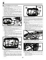
TO ADJUST BAGGER FULL LEVER/EXTENSION
• Before adjusting, tractor engine must be shut off and parking
brake engaged.
Slide bagger full extension to the desired position (15).
• For the heaviest/wet grasses, slide extension all the way in.
• For the lightest/driest grasses, pull extension all the way out.
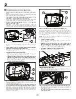
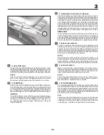
TO ADJUST PIVOT BRACKETS (12)
The tractor comes from the factory with the bagger pivot bracket
preset in a fixed position. If necessary, this position can be adjusted
to maintain a consistent gap (A) between the fender and the bag-
ger assembly top. An ideal gap is approximately 0.2” (5.1mm).
NOTE:
As desired, the pivot bracket on either side can be ad-
justed in this manner.
• Remove bagger assembly.
• Remove fixed (3/8”-16) bolt (13). Bolt is no longer necessary
for use with tractor.
• Loosen remaining three (3/8”-16) bolts (14) so that pivot
bracket (12) can slide. Do not remove bolts.
• Adjust pivot bracket (12) to desired position and retighten
three (3/8”-16) bolts (14).
• Check the gap (A) between fender and bagger.
• Readjust if necessary.
15
11
10
9
5
6
7
8
4
14
12
13
A

