


9
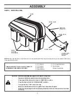
ASSEMBLY
WA
RN
ING
Do
no
t o
pe
rat
e m
ow
er
un
les
s c
on
tai
ne
r is
pr
op
erl
yis
ns
tal
led
.Co
nta
ine
r is
su
bje
ct
to
we
ar
an
d d
eti
eri
ora
tio
n.
Ch
ec
k b
ag
fre
qu
en
tly.
Re
pla
ce
wh
en
cra
cke
d o
r d
am
ag
ed
. U
se
on
ly a
re
co
mm
en
de
d r
ep
lac
em
en
t c
on
tai
ne
r.
WA
RN
ING
Do
no
t o
pe
rat
e m
ow
er
un
les
s c
on
tai
ne
r is
pr
op
erl
yis
ns
tal
led
.Co
nta
ine
r is
su
bje
ct
to
we
ar
an
d d
eti
eri
ora
tio
n.
Ch
ec
k b
ag
fre
qu
en
tly.
Re
pla
ce
wh
en
cra
cke
d o
r d
am
ag
ed
. U
se
on
ly a
re
co
mm
en
de
d r
ep
lac
em
en
t c
on
tai
ne
r.
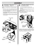
CONTAINER MOUNTING (See Fig. 7)
No hardware required
•
Install one container to left side first with warning to
outside of unit. Install another container to center
position and one in right position.
NOTE
: Right container should always overlap left container
at center supports.
•
Close cover and lock latch handles over center support
tubes.
6
Fig. 7
COVER LATCH
HANDLES
CONTAINER
WARNING
C O N T A I N E R
HANDLE
CONTAINER
WARNING
CENTER
SUPPORT
TUBES
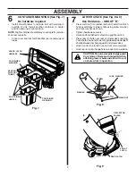
LOWER CHUTE (See Fig. 8 & 9)
Use Hardware - - GROUP "D"
•
Press weld nut into rubber latch and install two latch
hook assemblies to lower chute using screw, washer,
and lock washer as shown.
•
Tighten hardware securely.
•
Raise and hold deflector shield in upright position.
•
Place rear of chute over rear of mower deck opening.
Push chute down and forward to guide extended edge of
chute between discharge guard and mower deck.
•
Hook front latch into tab hole on front of mower deck.
•
Hook rear latch into flange hole on back of mower deck.
7
CAUTION: Do not remove discharge guard
from mower. Raise and hold guard when
attaching lower chute and allow it to rest
on chute while in operation.
Fig. 8
SCREW
WELD NUT
LATCH
WASHER
LOCK WASHER
REAR LATCH
F R O N T
LATCH
DEFLECTOR
SHIELD
Fig. 9
Summary of Contents for CG46A
Page 13: ...13 SERVICE NOTES ...


