background image

17

ROTARY LAWN MOWER - - MODEL NUMBER 7021CM (7021CMA) - PRODUCT NUMBER 954 22 40-88

1         532 17 65-55  

Control Bar

2         532 17 36-58  

Upper Handle, with Grip

3         532 17 41-10  

Lower Handle

4         532 17 95-85  

Rope Guide

5         873 80 04-00  

Locknut 1/4-20

6         532 13 19-59  

Handle Bolt

7         532 06 64-26  

Wire Tie

8         532 16 42-65  

Grip, Foam

9         532 15 41-32  

Hinge Bracket

10       532 18 55-89  

Mulcher Door

11       532 17 65-56  

Engine Zone Control Cable

12       532 75 06-34  

Hex Washer Head Screw

13       532 12 52-03  

Up-Stop Bracket

14       532 18 55-88  

Handle Knob

15       532 05 17-93  

Hairpin Cotter

16       532 14 72-86  

Hinge Rod

17       532 17 41-12  

Support Bracket

18       817 60 04-06  

Screw

19       532 18 92-78  

Axle Arm Assembly - LF

20       532 18 92-77  

Axle Arm Assembly - RF

21       532 18 89-87  

Rear Skirt

22       532 16 85-99  

Selector Spring - Front

23       532 18 66-12  

Rear Door Assembly Kit (Includes Springs)

24       873 93 05-00  

Locknut 5/16-18

25       532 17 41-05  

Handle Bracket Assembly (Left)

26       532 17 41-06  

Handle Bracket Assembly (Right)

27       532 85 18-56  

Screw 1/4-20 x 3/8

28       532 15 21-24  

Hinge Spring

29       532 16 57-04  

Wheel Adjusting Bracket - Front

30       532 18 39-01  

Spacer

31       532 18 55-95  

Clip on Discharge Guard

32       532 18 57-16  

Selector Spring - Rear

33       532 18 55-74  

Selector Knob

34       532 18 57-18  

Axle Arm Assembly - LR

36       532 16 08-28  

Shoulder Bolt 5/16-18

37       532 18 01-83  

Wheel Assembly, Rear

38       532 18 05-41  

Wheel Assembly, Front

39       532 08 39-23  

Flanged Locknut

40       532 18 01-23  

Hubcap

41       532 08 86-52  

Hinge Screw

42       532 16 57-66  

Spring (LH)

43       532 16 57-67  

Spring (RH)

44       532 18 41-93  

Door Bolt

45       532 15 04-06  

Hex Head Thread Rolling Screw 3/8-16 x 1

46       532 10 73-39  

Danger Decal

47       532 18 06-26  

Hubcap

48       532 18 57-17  

Axle Arm Assembly - RR

52       532 16 36-62  

Housing Assembly


(Includes Key Numbers 17, 18 and 46)

53       532 85 10-84  

Hex Head Screw 3/8-24 x 1-3/8 Grade 8

54       532 85 02-63  

Helical Lockwasher

55       532 85 10-74  

Hardened Washer

56      

532 17 50-64


21" Blade

57       532 18 45-90  

Blade Adapter

58       532 18 81-52  

O-Ring

59       532 08 83-48  

Washer, Flat  3/8

67       532 18 97-88  

Grass Bag

68       532 18 88-13  

Frame, Grass Bag

70              - - -           

Engine, Briggs & Stratton, Model Number 12H602


(Order parts from engine manufacturer)

71       532 13 20-04  

Nut, Hex  1/4-20

- -        532 16 23-00  

Warning Decal (Not Shown)

- -        532 18 99-72  

Owner’s Manual, English / French

NOTE:

 All component dimensions given in U.S. inches.

            1 inch = 25.4 mm

KEY    PART
NO.     NO.                 

DESCRIPTION        

KEY    PART
NO.     NO.                 

DESCRIPTION        

Summary of Contents for 7021CM

Page 1: ...7021CM Owner s Manual 532 18 99 72 Rev 2 04 12 04 BY Printed in U S A ...

Page 2: ...quire extra caution If you feel uneasy on a slope do not mow it DO Mowacrossthefaceofslopes neverupanddown Exer ciseextremecautionwhenchangingdirectiononslopes Remove obstacles such as rocks tree limbs etc Watch for holes ruts or bumps Tall grass can hide obstacles DO NOT Do not trim near drop offs ditches or embankments The operator could lose footing or balance Do not trim excessively steep slop...

Page 3: ...BILITIES 3 ASSEMBLY 4 OPERATION 5 8 MAINTENANCE SCHEDULE 9 MAINTENANCE 9 11 SERVICE AND ADJUSTMENTS 12 STORAGE 13 TROUBLESHOOTING 14 REPAIR PARTS 16 17 WARRANTY 20 WARNING Batteryposts terminalsand related accessories contain lead and lead compounds chemicals known to the State of California to cause cancer and birth defects or other reproductive harm Wash hands after handling WARNING Engine exhau...

Page 4: ... parts HOWTO SET UPYOUR LAWN MOWER TO UNFOLD HANDLE See Fig 1 IMPORTANT UNFOLD HANDLE CAREFULLY SO AS NOT TO PINCH OR DAMAGE CONTROL CABLES 1 Raise handles until lower handle section locks into place in mowing position 2 Remove protective padding raise upper handle sec tion into place on lower handle and tighten both handle knobs 3 Remove handle padding holding operator presence control bar to upp...

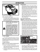
Page 5: ...RESENCE CONTROL BAR must be held down to the handle to start the engine Release to stop the engine STARTER HANDLE used for starting the engine HOUSING GRASS CATCHER PRIMER pumps additional fuel from the carburetor to the cylinder for use when starting a cold engine MULCHER DOOR allows conversion to discharge or bagging operation OPERATOR PRESENCE CONTROL BAR WHEEL ADJUSTER ON EACH WHEEL STARTER HA...

Page 6: ...levertoward wheel Movewheelupordowntosuityourrequirements Be sure all wheels are in the same setting NOTE Adjusterisproperlypositionedwhenplatetabinserts into hole in lever Also 9 position adjusters if so equipped allow lever to be positioned between the plate tabs The operation of any lawn mower can result in foreign objects thrown into the eyes which can result in severe eye damage Always wear s...

Page 7: ...in the Maintenance section of this manual CAUTION DO NOT overfill engine with oil or it will smoke on startup 1 Be sure lawnmower is level 2 Remove oil dipstick from oil fill spout 3 Engine holds 20 ounces of oil For type and grade of oil to use see ENGINE in the Maintenance section of this manual 4 Pour oil slowly Do not overfill Wait one minute to allow oil to settle Insert and tighten dipstick ...

Page 8: ...uce ground speed and or run the lawn mower over the area a second time For extremely heavy cutting reduce the width of cut by overlapping previously cut path and mow slowly For better grass bagging and most cutting conditions the engine speed should be set in the fast position Pores in cloth grass catchers can become filled with dirt and dust with use and catchers will collect less grass To preven...

Page 9: ...ed to operator abuse or negligence To receive full value from the warranty operator must maintain mower as instructed in this manual Some adjustments will need to be made periodically to properly maintain your unit At least once a season check to see if you should make any of the adjustments described in the Service and Ad justments section of this manual At least once a year replace the spark plu...

Page 10: ...OTE We do not recommend sharpening blade but if you do be sure the blade is balanced Care should be taken to keep the blade balanced An unbalanced blade will cause eventual damage to lawn mower or engine The blade can be sharpened with a file or on a grinding wheel Do not attempt to sharpen while on the mower To check blade balance drive a nail into a beam or wall Leave about one inch of the strai...

Page 11: ...conditions 1 Loosen screws and remove cover 2 Carefully remove cartridge 3 Clean by gently tapping on a flat surface If very dirty replace cartridge CAUTION Petroleumsolvents suchas kerosene are not to be used to clean cartridge Theymaycausedeterioration of the cartridge Do not oil cartridge Do not use pressurized air to clean or dry cartridge 4 Install cartridge then replace cover MUFFLER Inspect...

Page 12: ...rom lower handle CAUTION TO AVOID SERIOUS INJURY BEFORE PERFORMING ANY SERVICE OR ADJUSTMENTS 1 Release control bar and stop engine 2 Make sure the blade and all moving parts have completely stopped 3 Disconnect spark plug wire from spark plug and place where it cannot come in contact with plug ENGINE ENGINE SPEED Your engine speed has been factory set Do not attempt to increase engine speed or it...

Page 13: ...r carburetor cleaner products in the fuel tank or permanent damage may occur Use fresh fuel next season NOTE Fuel stabilizer is an acceptable alternative in mini mizing the formation of fuel gum deposits during storage Add stabilizer to gasoline in fuel tank or storage container Always follow the mix ratio found on stabilizer container Run engine at least 10 minutes after adding stabilizer to allo...

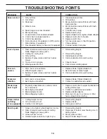
Page 14: ... 6 Cut at slower walking speed Poor cut 1 Worn bent or loose blade 1 Replace blade Tighten blade bolt uneven 2 Wheel heights uneven 2 Set all wheels at same height 3 Buildup of grass leaves and trash under 3 Clean underside of mower housing mower Excessive 1 Worn bent or loose blade 1 Replace blade Tighten blade bolt vibration 2 Bent engine crankshaft 2 Contact a qualified service center Starter r...

Page 15: ...15 SERVICE NOTES ...

Page 16: ...16 ROTARY LAWN MOWER MODEL NUMBER 7021CM 7021CMA PRODUCT NUMBER 954 22 40 88 ...

Page 17: ... 18 39 01 Spacer 31 532 18 55 95 Clip on Discharge Guard 32 532 18 57 16 Selector Spring Rear 33 532 18 55 74 Selector Knob 34 532 18 57 18 Axle Arm Assembly LR 36 532 16 08 28 Shoulder Bolt 5 16 18 37 532 18 01 83 Wheel Assembly Rear 38 532 18 05 41 Wheel Assembly Front 39 532 08 39 23 Flanged Locknut 40 532 18 01 23 Hubcap 41 532 08 86 52 Hinge Screw 42 532 16 57 66 Spring LH 43 532 16 57 67 Spr...

Page 18: ... at the time of pur chase all claims must be sent to the appropriate manufacturer 4 Lawn and garden attachments are covered by a third party which gives a warranty all claims for war ranty should be sent to the manufacturer and 5 Emission Control System components necessary to comply with CARB TIER II and EPA regulations which are manufactured by third party engine manufacturer SECTION 4 EXCEPTION...

Page 19: ...19 SERVICE NOTES ...

Page 20: ......

Reviews: