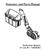
Husqvarna 42

©2012 HTC. All Rights Reserved.

Swainsboro, GA. Printed in U.S.A.

CONGRATULATIONS 

on the purchase of a new 

collection system. It has been designed, engineered 
and manufactured to give you the best possible 
dependability and performance.
Should you experience any problem you cannot 
easily remedy, please contact your nearest authorized 
service center/ department. They have competent, 
well-trained technicians and the proper tools for 
service and repairs.
Please read and retain this manual. The instructions 
will enable you to assemble and maintain your 
collection system properly. Always observe the 
SAFETY RULES.

KNOW YOUR BLOWER SYSTEM

READ THIS OPERATION MANUAL AND SAFETY 
RULES BEFORE ASSEMBLING OR OPERATING 
YOUR BLOWER SYSTEM. Compare the illustrations 
with the carton contents to familiarize yourself 
with the parts before starting the assembly. Study 
the operating instructions and safety precautions 
thoroughly to insure proper functioning of your Grass 
Catcher and to prevent injury to yourself and others. 
Save this manual for future reference.

The operation of any mower can result 
in foreign objects thrown into the eyes, 
which can result in severe eye damage. 
ALWAYS wear safety glasses or eye 
shields before starting your mower and 
while mowing. Standard safety glasses 
are recommended or a wide vision 
safety mask for over spectacles.

CAUTION

•  DO NOT operate mower with grass 

catcher partially installed.

•  Disengage blades and stop engine 

before leaving mower seat to 
empty containers, unclogging 
chutes, etc.

•  Close cover before starting.
•  Disengage mower blades when 

crossing driveways or gravel 
surfaces and other areas where 
thrown objects could be a hazard.

•  DO NOT attempt to vacuum cans 

or other potentially hazardous 
projectiles.

Summary of Contents for 42" Collection System

Page 1: ...Collection System 42 and 48 966805002 Operator and Parts Manual ...

Page 2: ... contents to familiarize yourself with the parts before starting the assembly Study the operating instructions and safety precautions thoroughly to insure proper functioning of your Grass Catcher and to prevent injury to yourself and others Save this manual for future reference The operation of any mower can result in foreign objects thrown into the eyes which can result in severe eye damage ALWAY...

Page 3: ...unting Brackets Bag of Hardware CAUTION BEFORE ASSEMBLING GRASS CATCHER TO MOWER Set parking brake Place motion control levers in NEUTRAL position Turn ignition key OFF and remove key Make sure the blades and all moving parts have completely stopped Disconnect spark plug and place wire where it cannot come in contact with plug NOTE When the terms RH right hand or LH left hand are used it refers to...

Page 4: ...ge 60 years and above are involved in a large percentage of riding mower related injuries These operators should evaluate their ability to operate the riding mower safely enough to protect themselves and others from serious injury Keep machine free of grass leaves or other debris buildup that can touch hot exhaust engine parts and burn Do not allow the mower deck to plow leaves or other debris tha...

Page 5: ... result in foreign objects being thrown into the eyes which can result in severe eye damage Always wear safety glasses or eye shields while operating your mower or performing any adjustments or repairs We recommend a wide vision safety mask over spectacles or standard safety glasses Use extra care in handling gasoline and other fuels They are flammable and vapors are explosive Use only an approved...

Page 6: ... Shoulder Bolt Support Assembly Drawbar A 8063 084 Kit Shoulder Bolt 2 Hang the support assembly over the replacement bolts and align the bottom pin into the drawbar Secure the bottom pin with a hairpin 8063 083 Draw Bar B 1 Slide the flanges of the support assembly in the slots in the drawbar ASSEMBLY Hairpin Drawbar B Support Assembly Hairpin 8063 086 8063 085 2 Pivot the assembly backwards to i...

Page 7: ...lower is sitting flush against the outside of the deck 6 Install the front mount bracket to the deck with the pin and hairpin cotter supplied with the kit Rear Mount Bracket Contact Area 8063 072 Outer Pulley Cover Pin Hairpin Cotter 8063 073 ASSEMBLY 1 Locate the rear adjustment nut on the discharge side of the deck To assure the right tighteness mark the front side of the nut 2 Using the mark as...

Page 8: ...T Rear of Deck Idler Pulleys Outer Pulley Twist in Belt Tension Release Arm 8063 074 4INSTALLING BELT COVERS 1 Place the deck belt shield on the deck over the drive pulley and secure with hardware removed from steel belt shield 2 Place retainer on the outer pulley cover 3 Align the tab end of the belt cover into the slot on the deck belt shield and the other end over the end of the outer pulley co...

Page 9: ...ainer bags Middle Chute 6MOUNTING COVER ASSEMBLY NOTE Assistance from another person may ease mounting the cover assembly to mower 1 Lift and rotate cover to align the cover brackets with support assembly tubes 2 Slide the cover down over the support tubes until secure 8063 082 8063 089 1 Position upper chute support against bagger inlet flush at outer edges See Illustration 2 Using support as a t...

Page 10: ...d always overlap the other container at the center tube 2 Close cover and lock latch handle over support tubes 8063 093 8INSTALLING SPACER PLUGS Remove center end caps Insert spacers and replace caps 9CONTAINER INSTALLATION CAUTION Do not leave grass in bagger containers Empty containers after each use and before storing Failure to do so may result in spontaneous combustion which could develop int...

Page 11: ...astic lawn bag with the edges of the bag draped over upper lip of the Container g Repeat for other container h Reinstall containers making sure right container overlaps left container at center supports i Close cover and secure latches over center support tubes Avoid cutting wet grass or in the morning while the dew is still heavy Grass clippings collected under these conditions tend to be sticky ...

Page 12: ... 3 4 8 6 7 23 9 10 11 12 13 14 15 16 17 18 19 20 21 22 5 24 25 26 27 28 29 30 31 32 31 34 35 36 37 38 39 40 41 42 43 44 45 46 44 48 49 50 51 52 53 55 56 57 54 55 49 53 38 15 53 44 48 48 47 55 48 4 54 52 33 42 47 58 BLOWER ...

Page 13: ...OOD 28 539 104763 1 RETAINER U TYPE 29 539 115667 1 KEY 3 16 x 30 539 125229 1 KEY 3 16 x 1 31 539 130317 1 PIN 32 539 130315 6 HCS 5 16 18 x 33 539 110321 2 HCS 3 8 24 x 1 GR 8 34 539 990209 1 HCS 5 16 18 x 1 35 539 990655 1 HCS 3 8 16 x 1 36 539 976949 1 HCS 3 8 16 x 1 37 539 108461 3 HCS 20 x 38 539 990643 2 HCS 20 x 7 8 39 539 990316 4 RHSNB 5 16 18 x 40 539 990645 1 RHSNB 3 8 16 x 1 41 539 99...

Page 14: ...14 REPAIR PARTS 6 5 14 4 3 13 1 9 2 12 10 7 8 21 11 15 13 16 17 18 19 21 21 18 17 20 CHUTES MOUNTS BELTS ...

Page 15: ...LD BELT 42 5 539 130347 1 BELT 48 539 132347 1 BELT 42 6 532 198128 1 SUPPORT TUBE ASSY 7 532 198364 1 SUPPORT TUBE ASSY 8 539 130309 1 COVER BELT 9 539 130349 1 DECAL BELT ROUTING 10 539 105743 1 DECAL NO STEP 11 539 104411 1 KNOB w STUD 12 539 108088 1 LATCH CHUTE 13 539 108085 2 SPACER SPLIT 14 532 176997 2 BOLT 3 8 16 SHOULDER 15 539 976952 1 SCREW 10 24 x 625 MACH 16 539 108081 1 SCREW SPEC 1...

Page 16: ...16 REPAIR PARTS 1 2 3 4 5 6 7 8 9 10 11 12 13 17 15 14 15 16 17 18 BAGGER ...

Page 17: ... SCREEN COVER 6 539 108097 4 PLUG TUBING END 7 522 801301 2 PLUG SPACER 8 532 192786 2 PIN HINGE 9 532 192550 1 SEAL COVER 10 532 192603 1 GASKET COVER 11 539 110281 1 SUPPORT CHUTE 12 539 112294 1 FLEX TRIM 13 539 108096 2 HAIR PIN 14 539 990627 2 HCS 5 16 18 x 1 15 539 976952 6 SCREW 10 24 x 5 8 16 539 112899 2 NUT 5 16 18 HEX FLG NYLOC 17 539 976977 6 NUT 10 24 CROWNLOCK 18 539 990188 4 WASHER ...

Page 18: ......

Page 19: ......

Page 20: ...115 429326 Rev C 2012 07 15 ...

Reviews: