background image

10

Fuel System

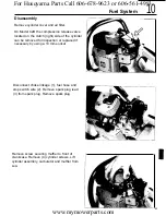
Install choke (1) and throttle 

(2) 

assemblies.

Install needle valve (3), spring (4), lever (5) and

pin (6). Secure with screw 

(7).

Metering lever must be level with metering

diaphragm mounting area of carburetor. Adjust

if necessary.

Install metering diaphragm and gasket. (Be

sure diaphragm is captured on needle lever.)

Install metering diaphragm cover with ventila-

tion hole facing cylinder. Secure with screws.

For Husqvarna Parts Call 606-678-9623 or 606-561-4983

www.mymowerparts.com

Summary of Contents for 242

Page 1: ...42 42D 242 Workshop Manual 531 03 01 21 For Husqvarna Parts Call 606 678 9623 or 606 561 4983 www mymowerparts com ...

Page 2: ...cluded in this manual Later editions are revised to include any prod uct changes that may have occurred Safety Statements The following safety statements are found throughout this manual and are designed to make you aware of potential hazards or unsafe practices WARNING Immediate hazards which can result in severe injury or death CAUTION Hazards or unsafe practices which can result in severe perso...

Page 3: ...Table of Contents P a g e N o Section Husqvarna Forest Garden 1995 1 For Husqvarna Parts Call 606 678 9623 or 606 561 4983 www mymowerparts com ...

Page 4: ...l 42 D Chain Pitch Drive Link Gauge Weight Model 242 Model 42 D Weight with 13 inch Guide Bar and Chain Model 242 Model 42 D 42 0 cc 2 5 cu in 42 0 mm 30 0 mm 15500rpm 13000 rpm 2900 rpm 3900 rpm Walbro HDA 34 0 5 Iitres 1 1 pints 3 7 cc rein at 9000 rpm 0 27 Iitres 0 55 pints SEM AM7 0 3 mm 012 inch NGK BPMR6A CHAMPION RCJ7Y 0 5 mm 02 inch 65 watts at 10000 rpm NA 13 18 inches 33 46 cm 7 tooth 19...

Page 5: ...01 50271 13 01 5027114 01 Assembling pliers spark plug Puller screw Crankshaft installer Piston stop Pressure gauge Wrench 11 mm Piston ring compressor Seal Installer Drift Hook for fuel filter Oil gear puller Air gap gauge Holding bar for flywheel puller Crankcase puller Test plug Tachometer For Husqvarna Parts Call 606 678 9623 or 606 561 4983 www mymowerparts com ...

Page 6: ...ch cover assembly Remove hand guard retaining screw Rethread screw into pivot sleeve two turns Press on screw head to drive out inner pivot sleeve half Turn cover to opposite side Using a suitable punch remove outer half of pivot sleeve Separate hand guard from cover 4 For Husqvarna Parts Call 606 678 9623 or 606 561 4983 www mymowerparts com ...

Page 7: ...ver plate WARNING Wear eye protection when removing spring to prevent injury Using a screwdriver pry out brake spring Using a punch drive out knee link retaining pin 5 For Husqvarna Parts Call 606 678 9623 or 606 561 4983 www mymowerparts com ...

Page 8: ...or damage or wear The brake band thickness should not be less than 0 75 mm 030 when measured at any point along the band The brake band must be replaced if the band is damaged or worn less than minimum thick ness If brake band requires replacement remove screw and replace band 6 For Husqvarna Parts Call 606 678 9623 or 606 561 4983 www mymowerparts com ...

Page 9: ... link in cover Install knee link assembly and roll pins Install spring on knee link mechanism WARNING Wear eye protection when installing spring to prevent injury With screwdriver positioned as shown press spring into place I 7 For Husqvarna Parts Call 606 678 9623 or 606 561 4983 www mymowerparts com ...

Page 10: ...cover plate and secure with 4 screws Position hand guard on clutch cover Press pivot sleeve halves into place Install and tighten screw Disengage chain 8 For Husqvarna Parts Call 606 678 9623 or 606 561 4983 www mymowerparts com ...

Page 11: ... ground and start the engine While holding the saw with both hands apply full throttle Activate chain brake by turn ing left wrist against hand guard as shown Chain should stop immediately WARNING Avoid contact between any object and the guide bar tip Contact can cause the chain and guide bar to suddenly move upward and backward toward the user Use both hands on the handles Follow all safety preca...

Page 12: ...out pin and remove throttle lockout Assembly Install throttle lockout and secure with pin Chain Catcher Inspect chain catcher If damage is evident remove screw and replace chain catcher 10 For Husqvarna Parts Call 606 678 9623 or 606 561 4983 www mymowerparts com ...

Page 13: ...ord out approximately 30 cm 1 2 and position in starter pulley recess Carefully allow pulley to rotate counterclockwise until spring tension has been relieved Remove screws 4 from guard ring 1 I I 11 For Husqvarna Parts Call 606 678 9623 or 606 561 4983 www mymowerparts com ...

Page 14: ...thdraw starter pulley WARNING Wear eye protection when removing spring to prevent injury Position starter so spring side is toward bench Tap housing down on bench sharply to remove recoil spring Clean all starter parts and check for wear or damage 12 For Husqvarna Parts Call 606 678 9623 or 606 561 4983 www mymowerparts com ...

Page 15: ...n Using thumbs care fully install new recoil spring into place Install starter cord into pulley as shown Melt cord end to seal knot If knot is too large it may interfere with starter pawls Thread starter cord through retaining rinq and eyelet as shown Attach starter handle to rope 13 For Husqvarna Parts Call 606 678 9623 or 606 561 4983 www mymowerparts com ...

Page 16: ...in pulley IMPORTANT Starter pulley must be flush against recoil spring Secure starter pulley with washer and screw Install guard ring with screws Pull starter han dle out and stop starter pulley with thumb Lift cord into pulley recess then preload spring by turning pulley three turns clockwise 14 For Husqvarna Parts Call 606 678 9623 or 606 561 4983 www mymowerparts com ...

Page 17: ...ecoil spring fully tightens With starter handle extended approximately 30 cm 1 2 from housing position starter against saw Release starter handle to allow the pulley to fit within the starter pawls on flywheel Secure starter with screws 15 For Husqvarna Parts Call 606 678 9623 or 606 561 4983 www mymowerparts com ...

Page 18: ...is the spark across the spark plug electrode appears to be weaker 0 5mm 020 Checking the Spark Remove and clean spark plug Check spark plug electrode gap Spark plug gap should be 0 5 mm 020 If electrodes are worn spark plug must be replaced With ON OFF switch in ON position ground spark plug to cylinder and pull starter handle A spark should appear across the electrodes 16 For Husqvarna Parts Call...

Page 19: ...d pull starter handle spark appears stop switch is faulty and musl be replaced If no spark appears check high tension leads connections and contacts for dirt wear and or damage If Using air gap gauge P N 5025134 02 check air gap between flywheel magnet and ignition module Air gap should be 0 3 mm 012 17 For Husqvarna Parts Call 606 678 9623 or 606 561 4983 www mymowerparts com ...

Page 20: ...ark replace coil Replacement of the Ignition Module Remove leads from ignition module Remove screws and ignition module Position new igni tion module as shown and install but do not tighten screws For Husqvarna Parts Call 606 678 9623 or 606 561 4983 www mymowerparts com ...

Page 21: ... Remove air gap gauge Connect blue ON OFF switch lead 1 and red coil lead 2 to ignition module Be sure to route all leads away from flywheel Replacement of the Coil Remove high tension lead from spark plug Remove ignition module lead and screws Remove coil Position new coil as shown and secure with screws Connect ignition module lead to coil 19 For Husqvarna Parts Call 606 678 9623 or 606 561 4983...

Page 22: ...ough rubber cover and install contact spring in guide hole and secure with assembling pliers Slide rubber cover over contact spring Removal of the Flywheel 20 Remove spark plug and thread piston stop P N 5025033 01 into spark plug hole until tight For Husqvarna Parts Call 606 678 9623 or 606 561 4983 www mymowerparts com ...

Page 23: ...ywheel with the M5 screws Ensure puller P N 5025026 01 is centered then tighten puller screw and lightly tap puller and remove flywheel On G series saws models with heated han dles the generator is now visible and can be removed The sealing ring holder is located behind the generator 1 21 For Husqvarna Parts Call 606 678 9623 or 606 561 4983 www mymowerparts com ...

Page 24: ...Installation Install flywheel key in crankshaft keyway and install flywheel Thread piston stop into spark plug hole until tight Install flywheel washer and nut Torque flywheel nut to 24 29 Nm 17 21 ft Ibs Install starter pawls Remove piston stop IMPORTANT Starter pawls must move freely 22 For Husqvarna Parts Call 606 678 9623 or 606 561 4983 www mymowerparts com ...

Page 25: ... side of the saw Checking the Switch Remove lead from switch Connect ohmmeter to crankcase 1 and lead connector 2 Slide switch to ON and then OFF position When the switch is in the ON position the needle should move When the switch is in the OFF position the needle should show no movement Handle Element Oxidation of lead connections and rear socket are common causes of element failure Clean elemen...

Page 26: ...ating System Test both rear and front handles as follows With heater switch in the OFF position con nect meter between points 1 and 2 Meter should read 5 1 5 7 ohms Checking the Generator WARNING Never start chain saw without bar chain and clutch cover installed The clutch could come loose and cause severe injury A voltmeter capable of reading AC voltage is needed to test generator Start saw and m...

Page 27: ...ove spark plug Thread pis ton stop P N 5025033 01 into spark plug hole until tight Loosen the clutch turn wrench in direction of arrow clutch has left hand threads Remove clutch drum On 242 models remove rim sprocket 25 For Husqvarna Parts Call 606 678 9623 or 606 561 4983 www mymowerparts com ...

Page 28: ...Centrifugal Clutch Dismantle the clutch spring Use a pair of pliers P N 5025049 01 and a small screwdriver and poor function 26 For Husqvarna Parts Call 606 678 9623 or 606 561 4983 www mymowerparts com ...

Page 29: ...g in one of the clutch shoes so that the spring end loop lies in the middle of the shoe and mount it to the hub Place an addi tional clutch shoe on the hub Fit the remaining clutch shoe Use a pair of pliers P N 5025049 01 and a screwdriver I r 27 For Husqvarna Parts Call 606 678 9623 or 606 561 4983 www mymowerparts com ...

Page 30: ...secure on crankshaft Apply grease to needle bearing through hole in crankshaft Remove piston stop Install spark plug and cylinder cover Install bar chain and clutch cover WARNING Never start chain saw without bar chain and clutch cover installed The clutch could come loose and cause severe injury 28 For Husqvarna Parts Call 606 678 9623 or 606 561 4983 www mymowerparts com ...

Page 31: ... three screws from oil pump Thread two M5 screws into pump housing as shown Tighten screws alternately half a turn each time until pump housing comes loose Remove pump housing and M5 screws Note Removal of the oiler also removes dust cover washer on the crankshaft the Lift oil suction hose and filter from oil tank and clean or replace oil pick up filter For Husqvarna Parts Call 606 678 9623 or 606...

Page 32: ...17 com pletely onto worm gear clockwise Screw puller bolt into sleeve and remove worm gear from crankshaft Tap pump housing against sturdy surface to remove sealing plug and pump piston 30 For Husqvarna Parts Call 606 678 9623 or 606 561 4983 www mymowerparts com ...

Page 33: ...ove of adjusting screw Tighten lock screw 2 Press in sealing plug 3 and install rubber output sleeve 4 Thread worm gear into puller sleeve until flush with end of sleeve Place sleeve with gear over the end of the crankshaft Tap sleeve down with a plastic hammer until gear contacts the shoul der on the crankshaft Place suction hose with filter in oil tank opening I For Husqvarna Parts Call 606 678 ...

Page 34: ...roleum grease Install oil pump and secure with screws Install washer with labyrinth seaI against pump Using a seal driver securely seat the washer Install clutch assembly bar chain and guide bar cover 32 For Husqvarna Parts Call 606 678 9623 or 606 561 4983 www mymowerparts com ...

Page 35: ... chain bar cylinder cover air filter and starter assembly Disconnect fuel hose On G models discon nect leads from generator to handles at con nectors Remove four shock mount screws Separate fuel tank assembly and front handle from powerhead Remove the four shock mounts using 11 mm spanner P N 5025067 01 Install and secure new shock mounts with 11 mm spanner IMPORTANT All 4 shock mounts must be rep...

Page 36: ...ressure should drop to 20 kPa 2 psi within 60 seconds NOTE Rate at which pressure drops can vary depending on type of two stroke oil used in fuel Replacement of the Vent Remove fuel tank cap completely Using a curved needle nose pliers grip vent tube and push vent out through passage Using a suitable punch push new fuel tank vent into place Some vents are threaded and require a screwdriver For Hus...

Page 37: ...filter and fuel filter before adjusting carburetor There are three adjustment screws on the carburetor L H T Low speed screw High speed screw Idle speed screw Turn screws L and H clockwise until lightly seated Turn screw L counterclockwise 1 1 2 turns Turn screw H counterclockwise 1 1 4 turns _ e 35 For Husqvarna Parts Call 606 678 9623 or 606 561 4983 www mymowerparts com ...

Page 38: ...in doesn t rotate at idle Adjust screw H for optimum cutting perfor mance under load Using a tachometer ensure maximum no load rpm does not exceed 14000 for 42 42D models and 15500 for 242 models caution Do not adjust carburetor less than 7 8 turn open on H needle this can cause an over speeding condition and possible lack of lubrication Removal of Carburetor Remove cylinder cover Remove air filte...

Page 39: ...isassembly Remove screws 1 Remove metering diaphragm cover 2 and metering diaphragm 3 Connect pressure gauge P N 5025038 01 to fuel hose nipple and submerge carburetor in a container of non flammable clear solvent Test pressure at permitted 50 kPa 7 psi No leakage I For Husqvarna Parts Call 606 678 9623 or 606 561 4983 www mymowerparts com ...

Page 40: ...lve Inspect needle valve 1 and lever or damage Replace if necessary 2 for wear Check shafts 1 choke and throttle plates 2 springs 3 and fast idle levers 4 for wear or damage Replace if necessary For Husqvarna Parts Call 606 678 9623 or 606 561 4983 www mymowerparts com ...

Page 41: ...ea is clean and exercise extreme care during disassembly cleaning and reassembly of the carburetor Drill a small hole in welch plug 1 and cup plug 2 Place a screwdriver in hole and pry out plugs Remove fuel screen 3 Remove adjust ing needles and springs 4 Clean carburetor housing and parts in suitable solvent and dry with low pressure air Assembly Install new fuel screen 3 Tap new welch plug 1 and...

Page 42: ...ver must be level with metering diaphragm mounting area of carburetor Adjust if necessary Install metering diaphragm and gasket Be sure diaphragm is captured on needle lever Install metering diaphragm cover with ventila tion hole facing cylinder Secure with screws For Husqvarna Parts Call 606 678 9623 or 606 561 4983 www mymowerparts com ...

Page 43: ...e with screw 2 Be sure fuel inlet fitting is angled correctly Pressure test carburetor as outlined earlier in this section No leakage is allowed Inspect manifold for damage and make sure impulse channel is open Replace if necessary 41 For Husqvarna Parts Call 606 678 9623 or 606 561 4983 www mymowerparts com ...

Page 44: ...f Carburetor Connect throttle linkage to carburetor Position carburetor as shown and tighten screws 1 Be sure fuel hose 2 is at least 95 mm 3 3 4 in above fuel tank and connect choke linkage 3 and as equipped heat switch lead 4 Install air filter and cylinder cover 42 For Husqvarna Parts Call 606 678 9623 or 606 561 4983 www mymowerparts com ...

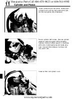
Page 45: ...tion or replaced if necessary by using a 13 mm socket Disconnect choke linkage 1 fuel hose and stop switch wire 2 Remove spark plug lead 3 from spark plug Remove spark plug Remove screw securing muffler to front of crankcase Remove 4 cylinder screws Lift cylinder assembly carburetor and muffler from saw 43 For Husqvarna Parts Call 606 678 9623 or 606 561 4983 www mymowerparts com ...

Page 46: ...aust port Check spark screen clean or replace Place piston ring in cylinder approximately 1 2 way down and check ring gap NOTE Proper ring gap is 0 25 0 30 mm 0 010 0 012 max 1 0 mm 0 040 For Husqvarna Parts Call 606 678 9623 or 606 561 4983 www mymowerparts com ...

Page 47: ...t pin into place Secure wrist pin with new cir clips Openings in circlips should be at either 12 o clock or 6 o clock Install new cylinder base gasket Secure muffler and carburetor to cylinder after replacing gaskets Apply oil to piston Install piston ring with open ing at piston pin Install piston ring compressor P N 5025070 01 on piston as shown I 45 For Husqvarna Parts Call 606 678 9623 or 606 ...

Page 48: ...inder with screws Be sure cylinder gasket is aligned properly before installing cylinder Secure muffler support to crankcase with screw Install spark plug and spark plug lead Connect choke linkage fuel hose and stop switch wire Install air filter and cylinder cover For Husqvarna Parts Call 606 678 9623 or 606 561 4983 www mymowerparts com ...

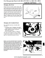
Page 49: ...Remove the wire Place a sleeve or washers over the stud Thread a stud nut down onto the stud to pull the stud into its seat Changing the Crankshaft Seals The crankshaft seals are accessible after removing The flywheel and if equipped the heated handle generator as instructed in Section 6 Ignition Systems and the oil pump as instructed in Section 5 Chain Lubrication Systems in Section 8 The seals c...

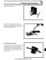
Page 50: ...e the four rubber elements and separate the crankcase from the tank Remove the seven screws retaining the Mount tool P N 5025161 01 on the clutch side of the crankshaft and crankcase Separate the crankcase halves by pressing the crankshaft out of the right crankcase half 48 For Husqvarna Parts Call 606 678 9623 or 606 561 4983 www mymowerparts com ...

Page 51: ...kshaft bearing then pressing the bearing out of the case Checking the Crankshaft The crankshaft is not serviceable and must be exchanged if defective Some crankshafts may have a slight blue discoloration around the crank pin This is a normal condition caused by the heat treatment around the crank pin hole during assembly 49 For Husqvarna Parts Call 606 678 9623 or 606 561 4983 www mymowerparts com...

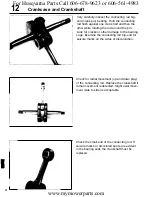
Page 52: ...he connecting rod big end for seizure marks on the sides or discoloration Check for radial movement up and down play of the connecting rod Replace the crankshaft if radial movement is detected Slight axial move ment side to side is acceptable I II 50 Check the small end of the connecting rod If seizure marks or discolored spots are evident in the bearing seat the crankshaft must be replaced For Hu...

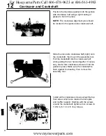
Page 53: ...f and install the crankshaft bear ing Make sure the bearing is fully seated Heat the bearing seat area of the drive right side crankcase half and install the crankshaft bearing ensuring it is fully seated Using assembly tool P N 5025030 07 pull the crankshaft into the ignition side crankcase half left Make sure the crankshaft is flush against the bearing 51 For Husqvarna Parts Call 606 678 9623 or...

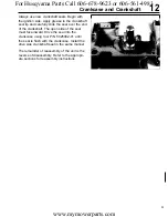
Page 54: ...ol Pull the crankshaft into the crankcase half while guiding the two halves together If neces sary start a few crankcase screws to hold the gasket in place Make sure the crankshaft is flush against the bearing then remove the assembly tool Install ail the crankcase screws except the top front screw which also retains the bar spike and muffler support Starting with the screws around the crankshaft ...

Page 55: ...e of the seal must face inward Drive the seal into the crankcase using tool P N 5025082 01 until the seal is flush with the crankcase Install the drive side crankshaft seal in the same manner The remainder of reassembly of the unit is the reverse of disassembly Refer to the appropri ate sections for reassembly instructions 53 For Husqvarna Parts Call 606 678 9623 or 606 561 4983 www mymowerparts c...

Page 56: ...For Husqvarna Parts Call 606 678 9623 or 606 561 4983 www mymowerparts com ...

Page 57: ...For Husqvarna Parts Call 606 678 9623 or 606 561 4983 www mymowerparts com ...

Page 58: ...NOTES For Husqvarna Parts Call 606 678 9623 or 606 561 4983 www mymowerparts com ...

Reviews: