®
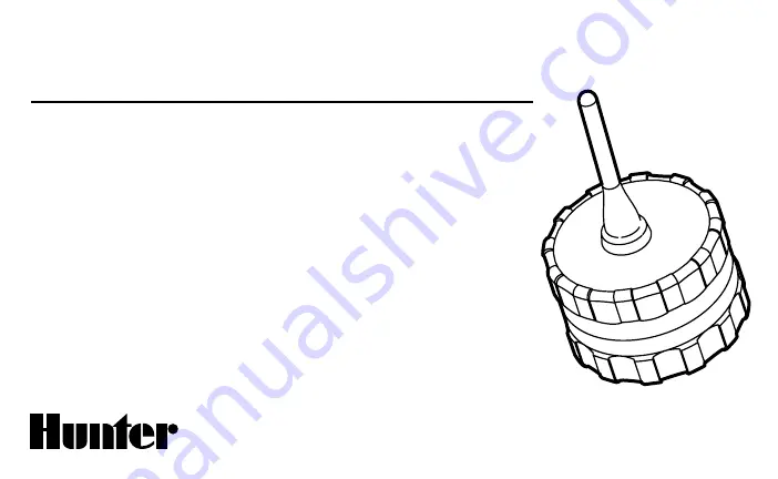
WVC
Wireless Valve Controller
Multiple Station Battery Powered
Irrigation Controller
Owner’s Manual and
Installation Instructions
Page 1: ... WVC Wireless Valve Controller Multiple Station Battery Powered Irrigation Controller Owner s Manual and Installation Instructions ...
Page 2: ......
Page 3: ...Latching Solenoids to the WVC 4 Radio Communication 5 Addressing the WVC with the WVP 6 Mounting the WVC to a Hunter Valve 7 Alternate Mounting Methods 8 Connecting a Weather Sensor 9 Programming the Controller 9 Specifications 10 FCC Notice 11 Industry of Canada Notice 12 CE Notice 12 ...
Page 4: ......
Page 5: ...s to power All programming and manual operations with the WVC are accomplished with the Wireless Valve Programmer WVP The WVP is a hand held programmer that allows you to create programs and conduct manual operations with WVC controllers in the field Because the WVP retrieves and transmits data via radio signals you never have to open a valve box to check the status or program your controllers The...
Page 6: ... into the battery holder 4 Wires for DC Latching Solenoids Leads are provided for wiring DC latching solenoids The red wires are numbered on top of the WVC to provide station identifi cation The black wire is the common wire 5 Weather Sensor Wires A Hunter Mini Clik or other micro switch type sensor can be connected to the WVC 6 Valve Mounting Clip Allows the WVC to be mounted directly to any Hunt...
Page 7: ...le memory that retains all program information when the battery is removed or in the event the battery is drained To install the battery 1 Unscrew the rear half of the WVC body to gain access to the battery compartment Installing the Battery 2 Snap the battery into the battery holder NOTE The battery holder is designed so that the battery can only be inserted in one direction 3 Make sure no water ...
Page 8: ...tion from the station wire 2 Remove 13mm of insulation from the common wire black wire on the WVC 3 Twist the red and black leads from the solenoid to the red and black leads on the WVC as shown in the figure 4 Make sure that waterproof connectors are used to secure all wire connections NOTE The maximum recommended distance from the WVC to any Hunter DC latching solenoid is approximately 100 feet ...
Page 9: ...he installation and the surrounding ter rain The WVP can send retrieve data to from the WVC up to 100 ft with the WVC installed in the valve box below ground level Radio range increases when the WVC is installed above ground Refer to the WVP Owner s Manual regarding radio communication Below Ground Installation For maximum radio range position WVC as high as possible see figure below ...
Page 10: ...it identification number Use the button to make sure that the WVP is in the transmit mode with the arrow on the display pointing towards the address icon see figure 1 3 Unscrew the rear half of the WVC body to gain access to the battery compartment 4 Install a standard 9 volt alkaline battery into the battery holder see Connecting the Battery 5 Wait for the red light inside the battery compartment...
Page 11: ...lve box to achieve maximum range for radio communication To mount the WVC to a valve Figure 2 1 Unscrew the existing solenoid from the valve 2 Screw the WVC latching solenoid into the valve bonnet 3 Attach the large end of the valve mounting clip to the middle of the WVC body mounting clip supplied with your WVC 4 Snap the small end of the valve mounting clip to the solenoid NOTE The total length ...
Page 12: ...controller is as high up in the valve box as possible but does not interfere with the top of the valve box cover 2 Drive two screws to secure the adapter to the side of the valve box 3 Attach the WVC to the mounting clip and slide it on the end of the mounting adapter Stake Mounting Method Figure 4 The universal mounting adapter can also be used to stake mount the WVC 1 Cut a section of 13mm diame...
Page 13: ...13mm of insulation from each wire Attach each wire to each of the wires of the weather sensor 3 Secure both wire connections with waterproof connectors Connecting a Weather Sensor The WVC is easy to program with its companion the WVP Wireless Valve Programmer The easy to understand push button design of the WVP allows you to step through the process of programming and activating manual watering wi...
Page 14: ...nd advance Programmable rain delay for 1 to 7 days Electrical Specifications Solenoids Operates 6 to 9 volt DC latching solenoids Battery Standard 9 volt alkaline battery not included one year minimum life Battery not required for pro gram backup Memory Non volatile for program data Weather sensor compatible Frequency of operation 900 MHz ISM band U S Aust 868 MHz Europe Dimensions WVC 3 25 D x 5 ...
Page 15: ...ce to radio communications However there is no guarantee that interference will not occur in a particular installation If this equipment does cause harmful interference to radio or televi sion reception which can be determined by turning the equipment off and on the user is encouraged to try to correct the interference by one or more of the following measures Reorient or relocate the receiving ant...
Page 16: ...C 100 WVC 200 and WVC 400 IC 2772 WVC The term IC before the certification registration number only signifies that the Industry of Canada technical specifica tions were met Operation is subject to the following two conditions 1 this device may not cause interference and 2 this device must accept any interference including interference that may cause undesired operation of the device CE Notice Hunt...