background image

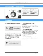
3. SmartWeight

®

 Pro Main Screen

1. Clip Weight Plane

6. SmartWeight® Menu
Button

2. Tape Weight Plane

7. Imbalance & Couple Force
Display

3. Context Sensitive Menu

8. SmartWeight Savings Total

4. Wheel Assembly
Display

9. Animated Instruction
Display

5. Start / Stop Button

4. Operation

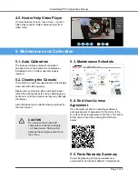
4.1. Getting Wheel On Balancer

CAUTION

Use two hands to maintain control
of the wheel

Slide proper collet onto spindle shaft. Position wheel
lift carriage (“lift”) at the end of the lift rail. Press the
foot pedal down to lower lift. Roll wheel onto the lift.
Raise foot pedal to raise wheel into position to slide
it on spindle. Center wheel on collet and clamp.
Keep lift under wheel and close hood. Lift will
automatically lower.

TIP

Allowing the balancer to lower lift
will speed up removal.

4.2. Remove Wheel From
Balancer

Place lift under wheel and raise it to wheel. Remove
wheel clamp. Slide lift with wheel on it to end of lift
rail. Use pedal to lower lift.

4.3. Centering Check

CenteringCheck® is an inspection or verification of
the wheel’s mount to balance to identify possible
centering errors, thus recognizing improper
measurements. From the main balance screen,
touch the “

CenteringCheck

” button.

4.4. Print Summary

From the main balance screen, select “Print” →
“Vehicle Summary”. The Vehicle Summary screen
will be displayed.

SmartWeight

®

 Pro Operations Manual

Page 6 of 8

Summary of Contents for SmartWeight Pro

Page 1: ...SmartWeight Pro Operations Manual 7641 T 09 21 ...

Page 2: ...RNING Warning Hazards or unsafe practices which could result in severe personal injury or death DANGER Danger Immediate hazards which will result in severe personal injury or death These symbols identify situations that could be detrimental to your safety and or cause equipment damage 2 2 Important Safety Instructions Electrical Do not operate equipment with a damaged cord or equipment that has be...

Page 3: ...r Do not place any tools weights or other objects on the safety hood while operating the balancer Verify that the wheel is mounted properly and that the wing nut is firmly tightened before spinning the wheel The safety hood must be closed before touching the green START button to spin the wheel Raise safety hood only after wheel has come to a complete stop If safety hood is raised before the spin ...

Page 4: ...e of wheel assemblies The laser is not a field serviceable part No maintenance is to be performed on the laser Wavelength 650nm 2 8 HammerHead TDC Laser Precaution optional equipment The TDC Top Dead Center Laser Indicator is a class 2M laser designed to aid in applying clip on weights The laser is not a field serviceable or adjustable part Use caution in regard to reflective materials around the ...

Page 5: ...ower the balancer OFF press the O side of the ON OFF switch 2 10 Equipment Specification Table 1 Electrical Voltage 208 240V 3 amp 50 60 Hz 1 ph NEMA 20 amp plug L6 20P Amperage Wattage Table 2 Air Air Pressure Requirements 100 175 psi 7 12 bar Approximate Air Consumption 4 CFM 110 Liters Minute Table 3 Atmospherics Temperature 32 F to 122 F 0 C to 50 C Relative Humidity Up to 95 Non condensing Al...

Page 6: ...ition to slide it on spindle Center wheel on collet and clamp Keep lift under wheel and close hood Lift will automatically lower TIP Allowing the balancer to lower lift will speed up removal 4 2 Remove Wheel From Balancer Place lift under wheel and raise it to wheel Remove wheel clamp Slide lift with wheel on it to end of lift rail Use pedal to lower lift 4 3 Centering Check CenteringCheck is an i...

Page 7: ...s such as diluting agent benzene or corrosive cleaner as they may damage the display ArmorAll wipes are a suitable cleaning product for the touch screen CAUTION Do not touch the screen with chemicals or solvents on fingers i e brake cleaner Doing so will damage the anti glare protector on the screen 5 3 Maintenance Schedule 5 4 End User License Agreement Use of equipment and it s operating softwar...

Page 8: ...two 2 years Normal wear items are not covered with the exception of batteries which are covered for a period of six 6 months Replacement parts purchased through the Hunter Service Center and no longer covered by machine warranty are warranted for a period of six 6 months Warranted parts may be replaced with new or refurbished parts at the discretion of Hunter Engineering Company This warranty does...

Reviews: