background image

41949-02  02/12/2008

40

2500 Frisco Avenue, Memphis, Tennessee 38114

Impreso en China

© 2008 Hunter Fan Company

  Garantía

Hunter Fan Company

Extractor de aire para baño

GARANTÍA LIMITADA

Hunter Fan Company establece la siguiente garantía limitada al usuario o comprador original de este Extractor de aire para baño Hunter:

Si alguna pieza de su Extractor de aire para baño Hunter (con excepción de las lámparas de vidrio y las bombillas) falla en cualquier momento 

dentro de un año después de la fecha de compra debido a una falla de material o mano de obra, repararemos o, a nuestra elección, reem-

plazaremos la pieza defectuosa sin costo de partes y mano de obra realizada en nuestro centro de reparaciones más cercano o en nuestro 

Departamento de servicio en Memphis, Tennessee. Después de este período de un año, usted será responsable de todos los costos de partes 

y mano de obra para reparaciones del Extractor de aire para baño, con excepción de reparaciones del motor, como se estipula a continuación.

Si el motor de su Extractor de aire para baño Hunter falla en cualquier momento dentro de cinco años después de la fecha de compra debido 

a una falla de material o mano de obra, la mano de obra y los materiales para reparar la falla serán proporcionados sin costo en nuestro centro 

de reparaciones más cercano o en nuestro Departamento de servicio en Memphis, Tennessee. Si no puede proporcionarse alguna parte de 

reemplazo, a nuestra elección, le reembolsaremos el precio de compra real de su Extractor de aire para baño o le proporcionamos uno de 

reemplazo sin costo. Después de este período de cinco años, usted será responsable de todos los costos de partes y mano de obra para repa-

raciones de cualquier componente del Extractor de aire para baño. 

SI EL USUARIO O COMPRADOR ORIGINAL DEJA DE POSEER EL EXTRACTOR DE AIRE, ESTA GARANTÍA Y CUALQUIER GARANTÍA 

IMPLÍCITA QUE PERMANEZCA EN EFECTO, INCLUYENDO PERO SIN LIMITARSE A TODA GARANTÍA IMPLÍCITA DE COMERCIABILIDAD 

O IDONEIDAD PARA UN PROPÓSITO PARTICULAR, QUEDA ANULADA. NO SE OFRECE NINGUNA GARANTÍA EXPRESA O IMPLÍCITA, 

INCLUYENDO CUALQUIER GARANTÍA DE COMERCIABILIDAD O IDONEIDAD PARA UN PROPÓSITO PARTICULAR, PARA LAS LÁMPA-

RAS DE VIDRIO O LAS BOMBILLAS O EL ACABADO DE CUALQUIER PARTE METÁLICA DEL EXTRACTOR DE AIRE PARA BAÑO.

ESTA GARANTÍA SUSTITUYE A TODAS LAS OTRAS GARANTÍAS EXPRESAS. LA DURACIÓN DE TODA GARANTÍA IMPLÍCITA, INCLUYENDO 

PERO SIN LIMITARSE A CUALQUIER GARANTÍA IMPLÍCITA DE COMERCIABILIDAD O IDONEIDAD PARA UN PROPÓSITO PARTICULAR, 

CON RESPECTO DE CUALQUIER MOTOR DE EXTRACTOR DE AIRE PARA BAÑO HUNTER U OTRA PARTE DEL VENTILADOR, ESTÁ 

EXPRESAMENTE LIMITADA AL PERIODO DE LA GARANTIA EXPRESA ESTABLECIDA ANTERIORMENTE PARA DICHOS MOTORES U 

OTRAS PARTES.

Esta garantía es nula si su Extractor de aire para baño no se adquiere e instala en los EE.UU. Esta garantía excluye y no cubre defectos, 

averías o fallas del Extractor de aire para baño Hunter que fueran ocasionados por reparaciones por parte de personas no autorizadas por 

nosotros, por el uso de piezas o accesorios no autorizados por nosotros, por mal uso, modificaciones, o daños al Extractor de aire

 para baño 

Hunter mientras esté en su posesión, o por un empleo no razonable, incluyendo la falta de suministrar un razonable y necesario manten-

imiento.

Para obtener servicio, contacte con el centro de servicio autorizado Hunter más cercano o con nuestro Departamento de servicio de Hunter 

Fan Company, en 2500 Frisco Avenue, Memphis, Tennessee 38114. Le agradeceremos que se ponga en contacto con nosotros antes de 

enviarnos su Extractor de aire para baño. Si le autorizamos a enviarlo, usted será responsable de todos los cargos de seguro y flete o de otras 

cargas del transporte a nuestra planta o centro de reparaciones. Devolveremos su Extractor de aire para baño Hunter con el flete prepagado. 

Su Extractor de aire para baño Hunter se debe embalar apropiadamente para evitar daños durante el tránsito ya que no seremos responsables 

de dichos daños. Al solicitar un servicio de garantía, debe exhibir una prueba de su compra. El comprador debe presentar el recibo de compra 

u otro documento que establezca la prueba de su compra.

EN NINGÚN CASO HUNTER FAN COMPANY SERÁ RESPONSABLE DE DAÑOS PERJUDICIALES O ACCESORIOS.

ALGUNOS ESTADOS NO PERMITEN LIMITACIONES SOBRE LA DURACIÓN DE UNA GARANTÍA IMPLÍCITA O LA EXCLUSIÓN O 

LIMITACIÓN DE DAÑOS ACCESORIOS O PERJUDICIALES, POR LO QUE LA LIMITACIÓN O EXCLUSIONES ANTES MENCIONADAS 

PUEDEN NO APLICARSE A USTED.

LA GARANTÍA LE DA DERECHOS LEGALES ESPECÍFICOS, PERO USTED TAMBIÉN PUEDE TENER OTROS DERECHOS QUE VARÍAN 

DE ESTADO A ESTADO.

011_41949_Sp_2-12-08.indd   40

2/12/08   2:46:45 PM

Summary of Contents for Riazzi 83001

Page 1: ...2 12 2008 I n s t a l l a t i o n G u i d e 83001 Riazzi Bath Ventilator with Light READ and SAVE THESE INSTRUCTIONS ENGLISH See page 2 Espa ol Vea la p gina 21 011_41949_EngS_2 12 08 indd 1 2 12 08 2...

Page 2: ...e same time C A U T I O N W arning 1 Use this unit only in a manner intended by the manufacturer If you have questions contact the manufacturer 2 Before servicing or cleaning the unit switch power off...

Page 3: ...4 K 77520 01 L 65219 75184 01 133 96374 01 214 Extra Screws x2 D x2 3 8 Cable Connector 1 Turn off the power source Tools Needed Not supplied Estimated assembly time 30 to 60 minutes Before Installati...

Page 4: ...the housing 3 I F Remove the pre loaded screw tip covers Remove the wiring cover screw 6 Back out the pre loaded screw tips until flush with the side of the housing Remove the wiring cover Remove pack...

Page 5: ...ew Construction attaching to joist 10 B C Choose Installation Option For New Construction attaching to joist go to step A11 page 5 For New Construction suspended between joists go to step B11 page 8 F...

Page 6: ...ther Option A13 0 A16 Route wires through strain relief For supply connection use wires suitable for at least 90 C 194 F Connect wires as shown Connect 4 duct and vent to the outside Tape joints If du...

Page 7: ...THE WIRING HARNESS 0 0 0 0 A17 Reinstall the motor by inserting the tabs and pushing up into position Make sure the wires are not pinched between the motor and the housing 0 0 0 0 I A18 ON OFF A21 Tes...

Page 8: ...ween the screw head and the joist Screws are not provided New Construction suspended between joists B11 E F 1 8 bit B14 B15 F B13 Position the correct depth mark at the bottom edge of the joist based...

Page 9: ...White White Bare Copper Ground B19 Night Light Night Light Switch 1 AC In Main Switch 1 AC In Switch 2 AC In Option Fan Main Light Together Option B21 Connect 4 duct and vent to the outside Tape join...

Page 10: ...I B23 Reinstall the motor by inserting the tabs and pushing up into position Make sure the wires are not pinched between the motor and the housing B25 Turn on the power source ON OFF B26 B24 J Test th...

Page 11: ...ommodate the new motor housing 9 x 9 75 Cut out an opening for the housing Use the motor housing as a template to mark position Slide the mounting rails into brackets Position the correct depth mark a...

Page 12: ...joist Screws are not provided Attach the rails onto the screws Tighten screws Connect 4 duct and vent to the outside Tape joints If ducting does not fit securely an adapter may need to be purchased R...

Page 13: ...witch 1 AC In Switch 2 AC In Option Fan Main Light Together Option Tighten the strain relief screws Connect wires as shown C24 I H C23 G Install the wiring cover plate Make sure all wiring connections...

Page 14: ...source Test the motor If the motor does not run check the plug connection C29 E1 Go to step on page 17 to attach grille Reinstall the motor by inserting the tabs and pushing up into position Make sur...

Page 15: ...nd check to make sure the opening is large enough to accommodate the new motor housing 9 x 9 75 Move the housing into position above the ceiling Attach existing ducting to duct connector Tape joints I...

Page 16: ...20 J Connect wires as shown Reinstall the motor by inserting the tabs and pushing up into position Make sure the wires are not pinched between the motor and the housing Connect wiring harness DO NOT A...

Page 17: ...21 Test the motor If the motor does not run check the plug connection Turn on the power source Attaching the Grille Remove the thumbscrews Connect wiring harness DO NOT ALLOW THE FIXTURE TO HANG FROM...

Page 18: ...ax 60 watt A 15 bulbs Not Included E8 Turn glass dome assembly as shown until it locks into position E6 O E7 Attach thumbscrews WARNING To reduce the risk of electrical shock all 4 thumbscrews MUST be...

Page 19: ...diagram Problem Light does not come on Solution Replace the light bulb with a new bulb Turn power on replace fuse or reset breaker Check all plug connections to be sure they are secure Check the wiri...

Page 20: ...IS IN LIEU OF ALL OTHER EXPRESS WARRANTIES THE DURATION OF ANY IMPLIED WARRANTY INCLUD ING BUT NOT LIMITED TO ANY IMPLIED WARRANTY OF MERCHANTABILITY OR FITNESS FOR A PARTICULAR PURPOSE IN RESPECT TO...

Page 21: ...41949 02 02 12 2008 21 G u a d e i n s t a l a c i n Ventilador para ba o Riazzi 83001 con luz LEA y CONSERVE ESTAS INSTRUCCIONES Espa ol 011_41949_Sp_2 12 08 indd 21 2 12 08 2 46 25 PM...

Page 22: ...ci n Nacional de Protecci n contra Incendios NFPA la Asociaci n de Ingenieros Americanos en Calefacci n y Aire acondicionado ASHRAE y los c digos locales 5 Al cortar o taladrar en paredes o techo no d...

Page 23: ...1 214 Tornillos adicionales x2 D x2 Conector de cable de 3 8 1 Incluido 2 F J Apague la fuente de alimentaci n Herramientas necesarias no suministradas Tiempo estimado de ensamblaje entre 30 y 60 minu...

Page 24: ...biertas de las puntas de tornillo precargadas Retire el tornillo de la cubierta del cableado Retire las puntas de tornillo precargadas hasta que est n a nivel con el lado del alojamiento Retire la cub...

Page 25: ...viga seg n el espesor de su plancha de yeso Construcci n nueva fijaci n a la viga Escoja la opci n de instalaci n Para construcci n nueva fijaci n a la viga vaya al paso A11 p gina 25 Para construcci...

Page 26: ...Conecte los alambres como se muestra Conecte un ducto de 4 y ventile hacia el exterior Aplique cinta a las uniones Si el ducto no se ajusta firmemente puede ser necesario comprar un adaptador Instale...

Page 27: ...enda la fuente de alimentaci n Conecte el mazo de cables NO PERMITA QUE EL MOTOR CUELGUE DEL MAZO DE CABLES Vuelva a instalar el motor introduciendo las pesta as y levantando a su posici n Aseg rese q...

Page 28: ...plantilla Introduzca los tornillos dejando espacio entre la cabeza del tornillo y la viga No se proporcionan los tornillos Construcci n nueva suspendido entre vigas Ubique la correcta marca de profund...

Page 29: ...s tornillos Conecte los alambres como se muestra Conecte un ducto de 4 y ventile hacia el exterior Aplique cinta a las uniones Si el ducto no se ajusta firmemente puede ser necesario comprar un adapta...

Page 30: ...GUE DEL MAZO DE CABLES Vuelva a instalar el motor introduciendo las pesta as y levantando a su posici n Aseg rese que los alambres no se pellizquen entre el motor y el alojamiento Encienda la fuente d...

Page 31: ...acomodar el alojamiento del motor nuevo 9 x 9 75 Recorte una abertura para el alojamiento Utilice el alojamiento del motor como una plantilla para marcar la posici n Deslice los rieles de montaje en...

Page 32: ...los Fije los rieles con los tornillos Apriete los tornillos Conecte un ducto de 4 y ventile hacia el exterior Aplique cinta a las uniones Si el ducto no se ajusta firmemente puede ser necesario compra...

Page 33: ...ci n Ventilador y luz principal juntos Opci n Motor del ventilador C22 C24 I H C23 G Apriete los tornillos del aliviador de tensiones Conecte los alambres como se muestra Instale la placa de cubierta...

Page 34: ...retando los 2 tornillos Encienda la fuente de alimentaci n Pruebe el motor Si el motor no funciona verifique la conexi n del enchufe Vuelva a instalar el motor introduciendo las pesta as y levantando...

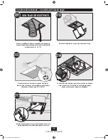
Page 35: ...posici n encima del techo Conecte el ducto existente con el conector de ducto Aplique cinta a las uniones Si el ducto no se ajusta firmemente puede ser necesario comprar un adaptador Instale el aloja...

Page 36: ...20 J H D17 G Conecte los alambres como se muestra Vuelva a instalar el motor introduciendo las pesta as y levantando a su posici n Aseg rese que los alambres no se pellizquen entre el motor y el aloja...

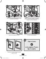
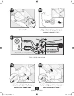
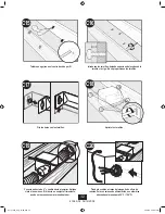
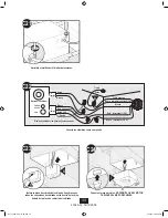
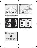
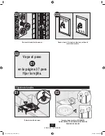
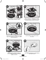
Page 37: ...1 M E2 Pruebe el motor Si el motor no funciona verifique la conexi n del enchufe Encienda la fuente de alimentaci n Fijaci n de la rejilla Retire los tornillos de mano Conecte el mazo de cables NO PER...

Page 38: ...vatios como m ximo No incluidas E8 Gire el conjunto de la pantalla como se muestra hasta que quede trabada en posici n E6 O E7 Instale los tornillos de mano ADVERTENCIA Para reducir el riesgo de desc...

Page 39: ...el diagrama de cableado Problema La luz no funciona Soluci n Reemplace la bombilla con una nueva Encienda la alimentaci n el ctrica reemplace el fusible o restablezca el interruptor autom tico Verifiq...

Page 40: ...O DE CUALQUIER PARTE MET LICA DEL EXTRACTOR DE AIRE PARA BA O ESTAGARANT ASUSTITUYEATODAS LAS OTRAS GARANT AS EXPRESAS LADURACI N DE TODAGARANT AIMPL CITA INCLUYENDO PERO SIN LIMITARSE A CUALQUIER GAR...

Reviews: