background image

42922-0 2/29/06

000000000000000000000000000000000000000000000000000000000

I

n

s

t

a

l

l

a

t

i

o

n


G

u

i

d

e

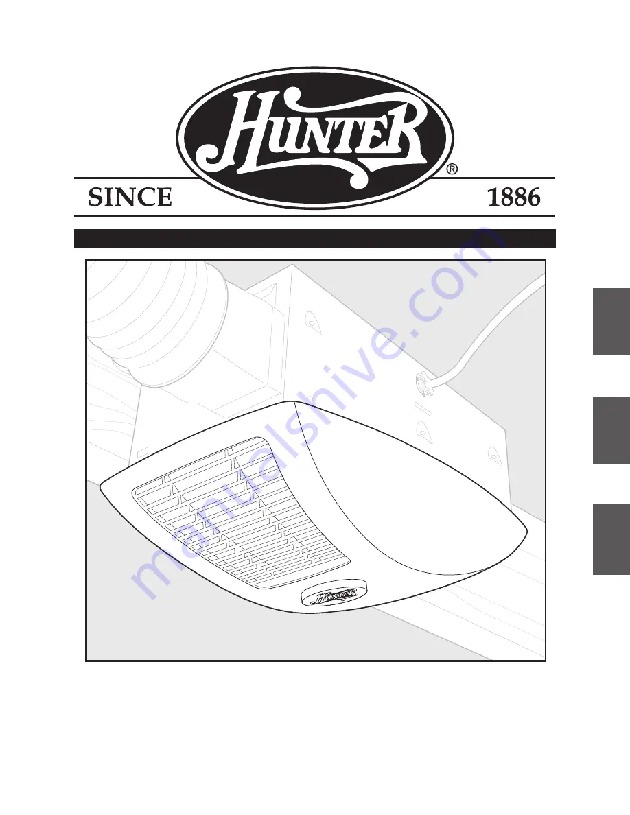
Bath Heater Fan Model 80500

READ and SAVE THESE INSTRUCTIONS

EN

G

LIS

H

Se

e p

ag

e 2

ES

pA

ñ

O

L

Ve

a l

a p

ág

in

a 2

FR

A

N

ç

A

IS

Co

ns

ult

er

 la

 p

ag

e 4

Summary of Contents for 80500

Page 1: ... 0 0 0 0 0 0 0 0 0 0 0 0 0 0 0 0 0 0 0 0 0 0 0 0 0 0 0 0 0 0 0 0 0 0 0 0 0 0 0 0 0 I n s t a l l a t i o n G u i d e Bath Heater Fan Model 80500 READ and SAVE THESE INSTRUCTIONS ENGLISH See page 2 Español Vea la página 21 français Consulter la page 41 ...

Page 2: ...2 Before installing servicing or cleaning the appliance disconnect the power by turning off the circuit breakers to the outlet box and associated wall switch location If you cannot lock the circuit breakers in the off position securely attach a prominent warning device such as a tag to the service panel 3 This appliance requires power supplied by a 20A dedicated circuit 4 This appliance must be gr...

Page 3: ... necessary when any heater is used by or near children or invalids and when ever the heater is left operating and unattended 13 To avoid motor bearing damage and noisy unbalanced blower wheel keep drywall spray con struction dust etc off power unit 14 Read specification label on product for further information and requirements 15 Do not insert or allow foreign objects to enter any ventilation or e...

Page 4: ...humbnut Finial Wiring Cover Screw Check all the parts If damaged call 1 888 830 1326 for replacement x8 E Mounting Screws Attachment Screws P Locknut x3 65218 01 000 NOTE Strain relief not supplied cable connector must be installed Attachment Screws F Switch Cover Plate 76121 A Turn off the power source Tools Needed Not supplied Estimated assembly time 30 to 60 minutes Before Installation Included...

Page 5: ... assembly from the housing Remove and discard the cardboard wedge D Loosen the wiring cover screw Remove the fan assembly from the housing C Remove the light assembly from the housing Remove the packing material H H Remove the wiring cover F ...

Page 6: ...accessible from above go to step C1 page 10 For Existing Construction accessible only from below go to step D1 page 12 Section A New Construction attaching to joist A4 Drive mounting screws supplied into joist or framing Position the correct depth mark at the bottom edge of the joist based upon the the thickness of your sheetrock 5 8 1 2 5 8 1 2 A3 5 8 1 2 5 8 1 2 A1 Pop out a wiring access slug O...

Page 7: ...Go to Section E Final Installation on page 14 A6 Install the wiring and the strain relief into the wiring access hole you made earlier 3 A5 Run the power supply wire through the strain relief leav ing 3 between the end of the wire and the strain relief Tighten the strain relief around the wire Section B New Construction suspended between joists B1 Pop out a wiring access slug OR ...

Page 8: ...ts Note the orienta tion of of the outer ends of the rails B2 5 8 1 2 5 8 1 2 B4 1 16 bit B5 Position the correct depth mark at the bottom edge of the joist based upon the the thickness of your sheetrock 5 8 1 2 5 8 1 2 B3 Insert mounting screws leaving space between the screw head and the joist Screws are supplied Attach the rails onto the screws B6 B7 ...

Page 9: ...he power supply wire through the strain relief leav ing 3 between the end of the wire and the strain relief Tighten the strain relief around the wire 5 8 1 2 5 8 1 2 B11 Connect 4 duct and vent to the outside Use duct tape to secure joints If ducting does not fit securely an adapter may need to be purchased Go to Section E Final Installation on page 14 ...

Page 10: ... bottom edge of the housing so that it will be flush with the sheetrock C2 Pop out a wiring access slug 7 1 4 C1 Remove an existing fan and check to make sure the opening is large enough to accommodate the new fan housing The opening needs to be 7 3 4 x 14 1 2 Section C Existing Construction accessible from above NO EXISTING FAN OR OR ...

Page 11: ...e between the screw head and the joist Screws are supplied Drill a pilot hole at the TOP of each outline AS SHOWN Attach the rails onto the screws C8 C9 Tighten screws 3 C10 Run the power supply wire through the strain relief leav ing 3 between the end of the wire and the strain relief Tighten the strain relief around the wire ...

Page 12: ...rlier C12 Connect 4 duct and vent to the outside Use duct tape to secure joints If ducting does not fit securely an adapter may need to be purchased Section D Existing Construction accessible from below Remove one of the wiring access slugs on the top of the housing Use a second wiring access plug if needed D1 D2 E F Remove the mounting rail brackets ...

Page 13: ...ain relief leaving 3 between the end of the wire and the strain relief Tighten the strain relief around the wire F D6 Connect 4 duct and vent to the outside Use duct tape to secure joints If ducting does not fit securely an adapter may need to be purchased D5 Install the wiring and the strain relief into the wiring access hole you made earlier Position the bottom edge of the housing flush with the...

Page 14: ...Light Black Black Green Blue Black Black Line Ground Ground SWITCH SUPPLIED WIRING COVER 120 VOLT SUPPLY Common Retrieve the wiring cover and connect the supply wires switch and plugs in the wiring cover as shown Section E Final Installation D9 Screw mounting screws into joist or framing Go to Section E Final Installation on page 14 ...

Page 15: ...me whether the housing is mounted to a joist or suspended between joists 5 8 1 2 5 8 1 2 5 8 1 2 E4 5 8 1 2 5 8 1 2 E5 Secure the fan by tightening the 2 attachment screws Reinstall the fan by inserting the tabs and pushing up into position Make sure the wires are not pinched between the motor and the housing 0 0 0 0 0 0 0 0 0 0 0 0 5 8 1 2 E6 Connect heater wiring harness DO NOT ALLOW THE HEATER ...

Page 16: ...o tighten the one locknut supplied Install two 60 watt max A 15 bulbs and a 7 watt max night light bulb bulbs not included 0 0 0 0 0 0 0 0 0 0 0 0 0 0 0 0 0 0 0 0 0 0 0 0 E11 5 8 1 2 5 8 1 2 E9 Connect light wiring harness DO NOT ALLOW THE LIGHT TO HANG FROM THE WIRING HARNESS 5 8 1 2 5 8 1 2 E8 Secure the heater by tightening the 4 attachment screws E12 TOP TOP TOP Install switch as shown ...

Page 17: ...rly turn off power at the source and check the wiring and plugs 0 0 0 0 0 0 0 0 0 0 0 0 0 0 0 0 0 0 0 0 0 0 0 0 0 0 0 0 0 0 0 0 0 0 0 0 0 0 0 0 0 0 0 0 0 0 0 0 E16 Position the bezel over the post in the center of the light assembly and secure in place with a thumbnut 0 0 0 0 0 0 0 0 0 0 0 0 0 0 0 0 0 0 0 0 0 0 0 0 0 0 0 0 0 0 0 0 0 0 0 0 0 0 0 0 0 0 0 0 0 E17 0 0 0 0 0 0 0 0 0 0 0 0 0 0 0 0 0 0 0...

Page 18: ...gent such as dishwashing liquid and a soft cloth to clean the bezel DO NOT use abrasive cloths steel wool pads or scouring powders TO CLEAN THE FAN HEATER ASSEMBLY Disconnect power to the unit by switching off the breaker or removing the fuse Turn the wall switch off Remove the bezel as described above Remove the three thumbnuts and the locknut from the lighting assembly Unplug the lighting assemb...

Page 19: ...S IN LIEU OF ALL OTHER EXPRESS WARRANTIES THE DURATION OF ANY IMPLIED WARRANTY INCLUD ING BUT NOT LIMITED TO ANY IMPLIED WARRANTY OF MERCHANTABILITY OR FITNESS FOR A PARTICULAR PURPOSE IN RESPECT TO ANY HUNTER FAN BATH HEATER FAN MOTOR OR OTHER FAN PART IS EXPRESSLY LIMITED TO THE PERIOD OF THE EXPRESS WARRANTY SET FORTH ABOVE FOR SUCH MOTORS OR OTHER PARTS This warranty is voided if your Hunter B...

Page 20: ...42922 01 12 29 06 20 ...

Reviews: