background image

20

41462-01   10/14/2005

®

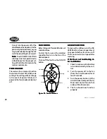
Figure 9f - Control Buttons

Figure 9f - Control Buttons

Figure 9f - Control Buttons

Figure 9f - Control Buttons

Figure 9f - Control Buttons

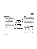
Do not turn the power off at the
circuit breaker, then back on, for the
previously installed fan(s), as you
may inadvertently change the DIP
switch code settings for it as well.

Note: 

Note: 

Note: 

Note: 

Note:  The DIP SWITCH SETTING
sub steps must be repeated as de-
scribed above for the proper set-
ting of the DIP switch code in the
receiver and remote.

POWER FAILURE

POWER FAILURE

POWER FAILURE

POWER FAILURE

POWER FAILURE

The receiver has a memory function
that retains the last DIP switch code
setting.  The setting will not change
in the event of power failure or if
power to the fan is inadvertently shut
off.

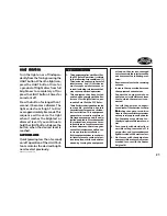
FAN CONTROL

FAN CONTROL

FAN CONTROL

FAN CONTROL

FAN CONTROL

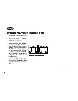
Refer to Figure 9f for identification of
control buttons.

To start the fan press the selected
speed button to run the fan at the
desired speed.

To turn off the fan. Press the FAN OFF
button.

AIRFLOW DIRECTION

AIRFLOW DIRECTION

AIRFLOW DIRECTION

AIRFLOW DIRECTION

AIRFLOW DIRECTION

To reverse the airflow press the RE-
VERSE button. Reverse operates at
any speed whether fan is on or off.
The fan returns to its set speed after
reversing.

If the fan is not functioning af-

If the fan is not functioning af-

If the fan is not functioning af-

If the fan is not functioning af-

If the fan is not functioning af-
ter installation:

ter installation:

ter installation:

ter installation:

ter installation:

1.

Check to make sure that battery
is installed correctly in the con-
trol.

2.

Turn the power off to the fan
(from the circuit breaker) for at
least 5 seconds.

3.

Turn the power back on (at the
circuit breaker) and push the Hi,
Med, and Low buttons–in that
order–within 20 seconds.

4.

The fan should now function
properly.

Fan High

Reverse

Light

Fan Medium

Fan Low

Fan Off

Summary of Contents for 41462-01

Page 1: ...1 41462 01 10 14 2005 InstallationandOperationManual ForHunterCeilingFans 41462 01 10 14 2005 ...

Page 2: ...2 41462 01 10 14 2005 ...

Page 3: ...iate the opportunity to supply you with the best ceiling fan avail ableanywhereintheworld Beforeinstallingyourfan recordthe following information for your records and warranty assistance Please refer to the carton and the Hunter nameplate located on top outside fan motor housing for the properinformation 2005 Hunter Fan Co 10 14 2005 Model Name ___________________ Catalog No ___________________ Se...

Page 4: ...Ready 6 Step2 InstallingTheCeilingPlate 8 Step3 AssemblingTheFan 10 Step 4 Hanging The Fan 11 Step 5 Wiring The Fan 12 Step6 AttachingTheCanopy 14 Step7 AssemblingFanBlades 15 Step8 AttachingTheSwitchHousing 16 Step9 RemoteControl 18 OperatingYourHunterFan 22 CleaningAndMaintenance 23 Troubleshooting 24 ...

Page 5: ...g fan be sure you candothefollowing Locate ceiling joist or other suit ablesupportinceiling Drill holes for and install wood screws Identify and connect electrical wires Lift 40 pounds If you need help installing the fan yourHunterfandealercandirectyou toalicensedinstallerorelectrician To reduce the risk of fire electrical shock or motor damage donotuseasolid statespeedcontrolwiththis fan UseonlyH...

Page 6: ... STEP 1 GETTING READY STEP 1 GETTING READY Site to help you select the best location for your fan The booklet alsoprovidesinformationtoensure your fan support and electric out let box meet UL approved safety codes for ceiling fans The instructions in this installation manual assume that you have used Guide to Choosing and Preparing a Ceiling Fan Site to pick the fan locationandmakecertaintheproper...

Page 7: ... use sturdy 3 4 diameter pipe to assure stability and wobble free performance Figure 1b Angle Mounting Figure 1b Angle Mounting Figure 1b Angle Mounting Figure 1b Angle Mounting Figure 1b Angle Mounting Figure 1a Standard Mounting Figure 1a Standard Mounting Figure 1a Standard Mounting Figure 1a Standard Mounting Figure 1a Standard Mounting 12 34 Max Pitch 12 8 Angle Mounting Angle Mounting Angle ...

Page 8: ...ood support structure through the outermost holes on the outlet box The pilot holes should be 9 64 in diameter by 2 3 4 in depth 2 Thread the lead wires from the outletboxthroughtheholeinthe middle of the ceiling plate 3 Position the three isolators be tween the ceiling plate and ceil ing by inserting the raised areas oneachisolatorintotheholesin the ceiling plate Refer to Figure 2a 4 Aligntheslot...

Page 9: ...late to e 2c Attaching Ceiling Plate to e 2c Attaching Ceiling Plate to 2 x 4 Brace 2 x 4 Brace 2 x 4 Brace 2 x 4 Brace 2 x 4 Brace 2 x 4 Brace CeilingJoist Ceiling OutletBox Ceiling Plate Flat Washer 3 Wood Screw For Angle Mounting Only For Angle Mounting Only For Angle Mounting Only For Angle Mounting Only For Angle Mounting Only Be suretoorienttheceilingplateso thatthearrowsontheplatepoint up t...

Page 10: ...pethroughthehanger bracket and canopy as shown in Figure3a Feedwiresfromthefan throughthepipe 2 Screwpipeintofanassemblyun til tight IMPORTANT Tighten allenheadpipesetscrewasshown inFigure3withtheincludedallen wrench Figure 3 Inserting Pipe through Figure 3 Inserting Pipe through Figure 3 Inserting Pipe through Figure 3 Inserting Pipe through Figure 3 Inserting Pipe through Hanger Bracket and Cano...

Page 11: ...hehangerbracketwith one hand and supporting the weightofthefanwiththeother hand raisethehangerbracketup flushtotheceilingplateasshown inFigure4b Twisthangerbracket clockwise and lock in place Figure 4b Hanging the Fan Figure 4b Hanging the Fan Figure 4b Hanging the Fan Figure 4b Hanging the Fan Figure 4b Hanging the Fan Figure 4a Adding Isolators to the Figure 4a Adding Isolators to the Figure 4a ...

Page 12: ...gconnections STEP 5 WIRING THE FAN STEP 5 WIRING THE FAN STEP 5 WIRING THE FAN STEP 5 WIRING THE FAN STEP 5 WIRING THE FAN W W W W WARNING ARNING ARNING ARNING ARNING Toavoidpossibleelectrical shock before wiring fan disconnect power by turn ing off the circuit breakers both to the outlet box and toitsassociatedwallswitch location Ifyoucannotlock the circuit breakers in the offposition securelyfas...

Page 13: ...In Ceiling White White Black Black Ceiling Plate Outlet Box 2 x 4 Brace Green Ground Wire from Hanger Pipe not present with flush mounting option Green Figure 5 Wiring Diagram Figure 5 Wiring Diagram Figure 5 Wiring Diagram Figure 5 Wiring Diagram Figure 5 Wiring Diagram ...

Page 14: ...CANOPY Figure 6 Attaching Canopy to Ceiling Figure 6 Attaching Canopy to Ceiling Figure 6 Attaching Canopy to Ceiling Figure 6 Attaching Canopy to Ceiling Figure 6 Attaching Canopy to Ceiling Plate Plate Plate Plate Plate RefertoFigure6 1 Raise the canopy and align the holesinthecanopywiththeholes intheceilingplate 2 Install and tighten the three canopyscrews ...

Page 15: ... barrel nuts and threedecorativescrewsasshown in Figure 7a 7b and 7c STEP 7 ASSEMBLING FAN BLADES STEP 7 ASSEMBLING FAN BLADES STEP 7 ASSEMBLING FAN BLADES STEP 7 ASSEMBLING FAN BLADES STEP 7 ASSEMBLING FAN BLADES Figur Figur Figur Figur Figure 7b e 7b e 7b e 7b e 7b 2 Remove the blade mounting screws and rubber shipping bumpers from the motor 3 Align the holes in the blade bracketandthecoverplate...

Page 16: ...UTION Make sure the upper switch housingissecurelyattachedto the switch housing mounting plate Failure to properly at tachandtightenallthreehous ing assembly screws could re sult in the switch housing and lightfixturefalling The switch housing is made up of twosections theupperswitchhous ing andthelowerswitchhousing A A A A ATT TT TT TT TTACHING THE UPPER SWITCH ACHING THE UPPER SWITCH ACHING THE ...

Page 17: ...ch Housing e 8c Lower Switch Housing Installation Installation Installation Installation Installation Upper Switch Housing 2 Wires for Optional Light Kit Lower Switch Housing Housing Assembly Screw INST INST INST INST INSTALLING ALLING ALLING ALLING ALLING ACCESSOR ACCESSOR ACCESSOR ACCESSOR ACCESSORY LIGHT Y LIGHT Y LIGHT Y LIGHT Y LIGHT KITS KITS KITS KITS KITS Toinstallanoptionallightkit replac...

Page 18: ...gur Figure 9b e 9b e 9b e 9b e 9b ROCKER LIGHT SWITCH ROCKER LIGHT SWITCH ROCKER LIGHT SWITCH ROCKER LIGHT SWITCH ROCKER LIGHT SWITCH 1 Break off the two tabs by push ing outward See Figure 9b 2 Remove the two screws holding theswitchcoverplate Donotre movethecoverplate 3 Orient the remote cradle as shown in Figure 9b Line up the two outer mounting holes with those on the switch insert screws don ...

Page 19: ...tchsettingsintheremote if you are using more than one re motecontrolledfaninthesamearea andwanttocontrolthemseparately 1 Atthecircuitbreakerorfusebox turnthepoweroffforthefanyou wanttochange 2 Slide the cover off the back of the remote and remove the bat tery The battery must be re movedwhenchangingdipswitch settings Refer to BATTERY IN STALLATION and Figure 9d DIPSwitch Setto 01110 DIPSwitch Sett...

Page 20: ...entificationof controlbuttons To start the fan press the selected speed button to run the fan at the desiredspeed Toturnoffthefan PresstheFANOFF button AIRFLOW DIRECTION AIRFLOW DIRECTION AIRFLOW DIRECTION AIRFLOW DIRECTION AIRFLOW DIRECTION To reverse the airflow press the RE VERSE button Reverse operates at any speed whether fan is on or off Thefanreturnstoitssetspeedafter reversing If the fan i...

Page 21: ...hthelim its for a Class B digital device pur suant to Part 15 of the FCC Rules Theselimitsaredesignedtoprovide reasonable protection against harmful interference in a residen tial installation This equipment generates usesandcanradiatera diofrequencyenergyand ifnotin stalledandusedinaccordancewith the instructions may cause harm fulinterferencetoradiocommuni cations However thereisnoguar anteethat...

Page 22: ...rd counterclock wise blade rotation in warm weather to cool the room with a direct breeze In winter having the fan draw air upward clock wise blade rotation will distrib utethewarmerairtrappedatthe ceilingaroundtheroomwithout causing a draft 4 If your fan wobbles when oper ating usetheenclosedbalancing kitandinstructionstobalancethe fan Figur Figur Figur Figur Figure 10a Air Flow Patter e 10a Air ...

Page 23: ...ANUF MANUFACTURER S ACTURER S ACTURER S ACTURER S ACTURER S PHONE NUMBER PHONE NUMBER PHONE NUMBER PHONE NUMBER PHONE NUMBER If you need parts or service assis tance please call 901 248 2222 or visit us at our WEB site at http www hunterfan com Caring for finishes For cleaning a soft brush or lint free cloth should beusedtopreventscratchingthefin ish A vacuum cleaner brush nozzle can remove heavie...

Page 24: ...PROBLEM PROBABLE CAUSE PROBABLE CAUSE PROBABLE CAUSE PROBABLE CAUSE PROBABLE CAUSE SOLUTION SOLUTION SOLUTION SOLUTION SOLUTION 1 Turnpoweron replacefuse orre set breaker 2a Loosen canopy check all con nections according to STEP 5 WIRING THE FAN turn power off before checking 2b Check the plug connection in the switch housing according to STEP 8 ATTACHING THE SWITCH HOUSING 3 Install fresh Alkalin...

Page 25: ...itch housing PROBLEM PROBLEM PROBLEM PROBLEM PROBLEM PROBABLE CAUSE PROBABLE CAUSE PROBABLE CAUSE PROBABLE CAUSE PROBABLE CAUSE SOLUTION SOLUTION SOLUTION SOLUTION SOLUTION Excessivewobbling Note Note Note Note Note When switching from medium tolowspeed youmaynoticesomefan wobble Whenthefanstabilizesatlow speed wobblewilldisappear 1 Unbalancedblades 2 Loose blades or blade iron 3 Fan not secure on...

Page 26: ...ION SOLUTION SOLUTION SOLUTION Notusingalkalinebatteries Remotebatterylifeseemsshort Replacewithalkalinebattery Remoteoperatesonlyatcloserange Batterytooweak Replace with new alkaline battery type 23A MN 21 or equivalent 1 RFinterference 2 ContinuingRFinterference 1 Turn OFF wall switch for 5 sec onds then turn back ON 2 Change DIP switch settings to a differentcode Followcomplete DIPswitchchanges...

Reviews: