background image

35

41457-01   7/2000

®

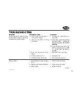
PROBLEM

PROBABLE CAUSE

SOLUTION

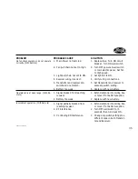
No functions operate or do not operate
correctly. (With Remote)

1. Main Power not restored.

2. Fan pull chain not set to High.

3. Light pull chain not set to ON.

4. Receiver wiring incorrect.

5. Transmitter and receiver dip

switches do not match.

6. Battery too weak.

1. Replace fuse.  Turn ON circuit

breaker.  Turn ON wall switch.

2. Turn OFF power at wall switch

or main electric panel.  Set fan
to High speed.

3. Set light kit to ON.

4. Verify wiring connections.

5. Set transmitter and receiver to

same dip switch setting.

6. Replace with new battery.

Operates only at close range. (With Re-
mote)

1. Signal blocked from reaching

receiver.

2. Battery too weak.

1. Extend antenna into ceiling box,

or move it for better reception.

2. Replace with new battery.

Inconsistent operation. (With Remote)

1. Signal partially blocked from

reaching receiver.

2. RF interference.

3. Continuing RF interference.

1. Extend antenna into ceiling box,

or move it for better reception.

2. Turn OFF wall switch for 5

seconds, then turn back ON.

3. Change dip switch settings to a

different code in both Transmit-
ter and Receiver.

Summary of Contents for 41457-01

Page 1: ...1 41457 01 7 2000 Installation and Operation Manual For Hunter Ceiling Fans 41457 01 7 2000 SINCE 1886 ...

Page 2: ...2 41457 01 7 2000 ...

Page 3: ...ore installing your fan record the following information for your records and warranty assistance Please refer to the carton and the Hunter nameplate located on top outside fan motor housing for the proper information 2000 Hunter Fan Co 7 2000 Model Name __________________ Catalog No ___________________ Serial No _____________________ Date Purchased ________________ Where Purchased ______________ ...

Page 4: ...mbly 10 Step 4 Assembling the Fan 12 Step 5 Hanging the Fan 14 Step 6 Installing the Remote 15 Step 7 Wiring the Fan 18 Step 8 Attaching the Canopy 20 Step 9 Assembling Fan Blades 21 Step 10 Attaching the Switch Housing 23 Step 11 Installing Light Fixture 26 Operating Your Hunter Fan and Remote 30 Cleaning and Maintenance 32 Troubleshooting 33 ...

Page 5: ...e support in ceiling Drill holes for and install wood screws Identify and connect electrical wires Lift 40 pounds If you need help installing the fan your Hunter fan dealer can direct you to a licensed installer or electrician To reduce the risk of fire electrical shock or motor damage do not use a solid state speed control with this fan Use only Hunter speed controls WARNINGS To avoid possible el...

Page 6: ...n for your fan The booklet also provides informa tion to ensure your fan support and electric outlet box meet UL approved safety codes for ceiling fans The instructions in this installation manual assume that you have used Guide to Choosing and Preparing a Ceiling Fan Site to pick the fan location and make certain the proper fan support and outlet box are in stalled CHECKING YOUR FAN PARTS Careful...

Page 7: ...mmended Flush Mounting Figure 1a fits close to the ceiling for low ceilings less than 8 feet high Standard Mounting Figure 1b hangs from the ceiling by a connec tor pipe included for ceilings 8 feet or higher For ceilings higher than eight feet you can purchase Hunter extension rods All Hunter fans use sturdy 3 4 diameter pipe to assure stability and wobble free perfor mance Angle Mounting Figure ...

Page 8: ...the hole in the middle may cause problems when installing the re mote and trying to close the canopy 3 Your fan comes with two neo prene noise isolators Position the isolators between the ceiling plate and ceiling by inserting the raised areas on each isolator into the holes in the ceiling plate Refer to Figure 2a Figure 2a Adding Isolators to Ceiling Plate Figure 2b Correct Position of Ceiling Pl...

Page 9: ...iling Outlet Box Ceiling Plate Flat Washer 3 Wood Screw 5 Place a flat washer on each of the two 3 screws and pass the screws through the slotted holes in the ceiling plate as shown in Figure 2c 6 Tighten the screws into the 9 64 pilot holes do not use lubricants on the screws Do not over tighten ...

Page 10: ...NG THE FAN If you are going to install the fan us ing the 12 long pipe for 9 ceilings or higher complete the steps below STEP 3 ASSEMBLING PIPE BALL ASSEMBLY 3 Remove the ball from the pipe 4 Remove the pin from the pipe Figure 3a Pipes Figure 3b Removing ball assem bly REMOVING BALL ASSEMBLY For the following steps refer to Figures 3b and 3c 1 Locate the 3 pipe ball assembly 2 Remove the position...

Page 11: ...o that it is level or straight CAUTION Do not overtighten the posi tioning screw as it may cause the ball to seat improperly re sulting in fan wobble and the fan hanging crookedly WARNING Failure to complete the steps above properly could result in the fan falling Figure 3c 12 pipe assembly CAUTION Make sure that the leadwire assembly is pointing straight up and away from the pipe WARNING To avoid...

Page 12: ...s a special coating on the threads Do not remove this coating the coating pre vents the pipe from unscrew ing Once assembled do not remove the pipe FLUSH MOUNTING For Low Ceilings 1 Tighten or remove pipe setscrew Fit the canopy over the hanger Figure 4a Inserting Pipe through Canopy Pipe Canopy Pipe Setscrew Figure 4b Placing Canopy and Washer Over Adapter Assembly Washer Canopy Adapter Top of Fa...

Page 13: ...c Positioning Assembly Washer Slots over Threaded Holes 3 Position the slots in the assem bly washer over the threaded holes in the adapter as shown in Figure 4c 4 Attach the canopy tightly to the fan assembly with three 8 32 assembly screws and lockwashers as shown in Figure 4d Assembly Screw and Lockwasher ...

Page 14: ... and associated wall switch location 2 Tilt and hang the assembled fan from the ceiling plate hooks Slip two rectangular canopy slots over ceiling plate hooks as shown in Figures 5a and 5b Note To hang the fan you must tilt the canopy to an almost verti cal position so the canopy slots come down over the ceiling plate hooks If you are installing the remote continue to STEP 6 INSTALLING THE REMOTE ...

Page 15: ...stall to control a receptacle WARNINGS Note This device complies with Part 15 of the FCC Rules Operation is subject to the following two condi tions 1 this device may not cause harmful interference and 2 this device must ac cept any interference re ceived including interfer ence that may cause undes ired operation SETTING UP THE TRANSMITTER 1 Remove the battery cover from the transmitter by pressi...

Page 16: ...periods of time 4 Replace the battery cover on the transmitter 5 Mount the remote holder using the two screws provided with the remote kit Slide out center piece on the holder to see screw holes Replace center piece after mount ing to wall Refer to Figure 6b 6 The transmitter can be placed on the remote holder for conve nience or safe keeping INSTALLING THE RECEIVER 1 Slide the dip switches to the...

Page 17: ...formance may be re duced Connect To Green wire from fan Bare ground wire Black wire from receiver Black supply wire White wire from receiver White supply wire White wire from receiver White wire from fan Black wire from receiver Black wire from fan Black White wire from receiver Black White wire from light Once receiver is installed and power is turned back on DO NOT pull the fan or light chains w...

Page 18: ...with one wall switch and the fan with an other two wall switches re quired Use connection 2 on page 19 if there is no separate wall switch power wire for the light fixture Note Wall switches not included continued 2 Connect the wires as shown in Figure 7a To connect the wires place the bare metal leads to gether Place a wire nut over the intertwined length of wire and twist clockwise until tight a...

Page 19: ...tlet Box 2 x 4 Brace Green Ground Wire from Hanger Pipe not present with flush mounting option 3 Wires From Fan Note Wall switch must be acceptable as a general use switch Connect Blk Wht Wire from fan to Wall Switch Wire for separate control of light fixture or Connect Blk Wht Wire from fan to Ceiling Black Wire if there is no separate Wall Switch Wire for the light fixture 1 2 Figure 7a Wiring T...

Page 20: ...iling plate Refer to Figure 8a 2 Install and tighten the two 10 32 x 1 2 mounting screws 3 For Standard and Angle Mounting Only In addition to sub steps 1 and 2 lift the fan housing towards the ceiling and rotate the fan until each canopy tab engages a groove in the hanger ball as shown in Figure 8b Note If the tabs are already en gaged do not rotate WARNING Failure to complete sub steps 1 through...

Page 21: ...own in Figure 9c Hunter fans use several styles of fan blade irons brackets that hold the blade to the fan 1 Your fan may include blade grom mets see Parts List If your fan has grommets insert them by hand into the holes as shown in Figure 9a 2 Attach each blade to blade iron using three blade assembly screws as shown in Figure 9b Some fans STEP 9 ASSEMBLING FAN BLADES If you used grommets the bla...

Page 22: ...ert one blade mounting screw through the blade iron as shown in Figure 9d and attach lightly to the fan In sert the second blade mounting screw then securely tighten both mounting screws Figure 9d Attaching Blade Irons to Hub of Fan Assembly ...

Page 23: ...two sections the upper switch hous ing and the lower switch housing ATTACHING THE UPPER SWITCH HOUSING 1 Partially install two 6 32 x 3 8 housing assembly screws into the switch housing mounting plate as shown in Figure 10a 2 Feed the upper plug connector through the center opening of the upper switch housing See Figure 10a 3 Align the keyhole slots in the up per switch housing with the hous ing a...

Page 24: ... hunter fan includes one of two lower switch housings Both lower switch housings are shown in Figures 10c and 10d The type of lower switch housing you have depends on whether your fan includes a light fix ture and if so what type of light fix ture it is Use table 10 1 to assist you If your fan has a lower switch hous ing as shown in Figure 10c and you ARE installing an accessory light kit or singl...

Page 25: ...d before connecting them together Incorrect connection could cause improper operation and damage to the product Figure 10e Plug Connection and Lower Switch Housing Installation Upper Switch Housing Upper Plug Connector Lower Plug Connector Lower Switch Housing Housing Assembly Screw 2 Place the lower switch housing assembly over the upper switch housing Align the side screw holes in the upper and ...

Page 26: ...utlet box and to its asso ciated wall switch location If you cannot lock the cir cuit breakers in the off po sition securely fasten a prominent warning device such as a tag to the service panel Connect house wiring to the fan before attaching the light fixture to the fan All wiring must be in accor dance with national and lo cal electrical codes and ANSI NFPA 70 If you are unfamiliar with wiring y...

Page 27: ...the black wire of the light kit Connect the white Figure 11a Removing Plug Button and Switch Housing Cap Lower Switch Housing Plug Button Switch Housing Cap 4 Screw the fixture into the lower switch housing Thread the lockwasher and nut provided over wire to the white wire of the light kit 6 Connect the upper plug connec tor from the motor to the lower plug connector in the lower switch housing as...

Page 28: ... the beginning of the first thread on the lampholder and notch on the locking ring to avoid cross threading the ring If the ring becomes hard to turn rotate the ring counter clockwise to loosen and reposition Do not force the ring on Note Both plug connectors are polarized and will only fit together one way Make sure that both connectors are properly aligned before connecting them together Incorre...

Page 29: ... Silencer Band Thumb screw Globe Thumbscrew Bulb Figure 11e Single Globe Fixture INSTALLING SINGLE GLOBE FIXTURE BULB AND GLOBE Refer to Figure 11e 1 Install light bulbs 2 Insert the globe around the bulb and into the fixture Install and tighten thumbscrews manually Do not overtighten INSTALLING INTEGRATED MULTI LIGHT FIXTURE BULBS AND GLOBES Refer to Figure 11f 1 Place silencer band around the ne...

Page 30: ...er to the fan 2 The pull chain controls power to the fan The chain has four set tings in sequence High Medium Low and Off Pull the chain slowly to change settings Release slowly to prevent the chain from recoiling into the blades Figure 12a Air Flow Patterns direct breeze In winter having the fan draw air upward clock wise blade rotation will distrib ute the warmer air trapped at the ceiling aroun...

Page 31: ...r ON Press and hold the light button for more than 0 7 second to dim or LOW MED HIGH Display Light Button Fan Button brighten the light Release the light button when the desired light level is reached The light dimmer range is 20 to 100 The Light key has auto resume so the brightness will stay the same as the last time it was turned OFF Refer to Figure 12c 3 Fan Operation Press the fan button to t...

Page 32: ...NE NUMBER If you need parts or service asssitance please call 901 248 2222 or visit us at our WEB site at http www hunterfan com Caring for finishes For cleaning a soft brush or lint free cloth should be used to prevent scratching the fin ish A vaccuum cleaner brush nozzle can remove heavier dust Surface smudges or an accumulation of dirt and dust can easily be removed by using a mild detergent an...

Page 33: ...ace 1 Blade brackets screwed loosely to motor 2 Blade screwed loosely to blade iron 3 Blade cracked PROBLEM PROBABLE CAUSE SOLUTION 1 Turn power on replace fuse or re set breaker 2a Loosen canopy check all connections according to STEP 7 WIRING THE FAN turn power off before checking 2b Check the plug connection in the switch housing according to STEP 10 ATTACHING THE SWITCH HOUSING 3 Push switch f...

Page 34: ...t seated in canopy tabs 4 Change to approved speed control 5 Hand tighten the light fixture screws Ensure that rubber noise isolators are installed 6 Check and tighten screws to the switch housing mounting plate and to the upper and lower switch housing 1 Use balancing kit included with fan 2 Tighten all screws 3 Turn power off support fan very carefully loosen canopy and hang correctly 4 Turn pow...

Page 35: ... kit to ON 4 Verify wiring connections 5 Set transmitter and receiver to same dip switch setting 6 Replace with new battery Operates only at close range With Re mote 1 Signal blocked from reaching receiver 2 Battery too weak 1 Extend antenna into ceiling box or move it for better reception 2 Replace with new battery Inconsistent operation With Remote 1 Signal partially blocked from reaching receiv...

Reviews: