background image

FIRE PANEL (FIELD WIRING)

16

DRY CONTACTS: NORMALLY CLOSED

S

C

C SA

FIRE RELAY

SB

-

+

12 - 40VDC

• On the Terminal Strip mounted to the outside of the VFD enclosure a
Jumper will be in place on terminals “S” and “C”.  Remove the Jumper from
terminals “S” and “C”.

• Connect the wires coming from the Fire Panel to terminals “S” and “C”.

NORMALLY UNENERGIZED

S

C

C SA

FIRE RELAY

SB

-

+

12 - 40VDC

• On the Terminal Strip mounted to the outside of the VFD enclosure a
Jumper will be in place on terminals “S” and “C”.  Remove the Jumper from
terminals “S” and “C”.

• Connect a wire from terminal “S” to “SB” on the Fire Relay Terminal Strip

• Connect a wire from terminal “C” to “C” on the Fire Relay Terminal Strip.

• Apply 12-40VDC from Fire Panel to Fire Relay Input. Relay has a 20mA
draw.

NORMALLY ENERGIZED

• On the Terminal Strip mounted to the outside of the VFD enclosure a
Jumper will be in place on terminals “S” and “C”.  Remove the Jumper from
terminals “S” and “C”.

• Connect a wire from terminal “S” to “SA” on the Fire Relay Terminal Strip.

• Connect a wire from terminal “C” to “C” on the Fire Relay Terminal Strip.

• Apply 12-40VDC from Fire Panel to Fire Relay Input. Relay has a 20mA
draw.

S

C

C SA

FIRE RELAY

SB

-

+

12 - 40VDC

180 THREET INDUSTRIAL ROAD | SMYRNA, TN 37214 | 1-844-591-FANS (3267) | HUNTERFAN.COM/INDUSTRIAL

Summary of Contents for XP 14

Page 1: ...PLY TO 15 FROM EACH FAN LOCATION PRIOR TO FAN INSTALLATION IF PLATINUM LEVEL INSTALLATION Full turnkey installation includes routing all electrical wire and conduit from each fan location to electrica...

Page 2: ...NCLUDED CERTIFICATIONS ETL Intertek certified to ANSI UL 507 and CSA C22 2 No 113 in North America Limited Lifetime on Airfoils 2 year Warranty parts only Rigid Mount with pre wired downrod Control Pa...

Page 3: ...lders when installing or cleaning the fan DO NOT insert foreign objects in between rotating fan blades Installation Adjustment Repair or Maintenance Must Be Performed By Qualified Personnel Follow all...

Page 4: ...tory and are ready to use No user adjustments are available Follow the included installation instructions when installing this device to ensure proper operation Do not make any changes to any part of...

Page 5: ...structure to withstand double the maximum hanging weight of the fan a professional structural engineer should perform a thorough evaluation of the building prior to purchasing the fans Hunter Industr...

Page 6: ...son cannot reach the rotating blades in any way Position fans so that the tips of the blades are at least 5 feet away from any area where a person may be able to extend outward to reach them Lights an...

Page 7: ...METER MINIMUM CLEARANCE FAN PLACEMENT FAN SPACING CHART A MIN MAX DIA A B XP 35ft 56ft 10 67m 17 07m 14ft 427cm 10ft 305 cm 12ft 366cm 8ft 244 cm 7ft 213 cm 25ft 40ft 7 62m 12 19m 30ft 48ft 19 14m 14...

Page 8: ...ot water or regular cleaning solutions DO NOT use chlorine or any chemicals containing chlorine or the blades may be damaged Retention System Check Each fan is installed with a retention system Every...

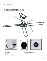
Page 9: ...9 IN THE BOX FAN COMPONENTS A B C A 1 Downrod B 1 Motor C 4 Blades D 1 Control Panel E 1 Standard Control F 1 Communication Cable G 1 Installation Manual not shown D E F...

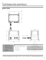
Page 10: ...ion Can be daisy chained to control up to 5 fans 3 5 LCD Touchscreen Alert Readouts Plug n Play design Standard junction box Simple flush mounting 2 73 69 31 2 00 50 80 3 95 100 31 3 05 77 44 3 55 90...

Page 11: ...y from screen Most cost effective network controller NUMBER OF FANS CONTROLLED ACTIVE DISPLAY AREA RESOLUTION DIMMING PROTECTION CLASS INPUT VOLTAGE UP TO 10 FANS 4 3 DIAGONALLY 480 X 272 DIAGONAL DIM...

Page 12: ...heduling grouping and fan naming Fan diagnostics directly from screen NUMBER OF FANS CONTROLLED ACTIVE DISPLAY AREA RESOLUTION DIMMING PROTECTION CLASS INPUT VOLTAGE UP TO 30 FANS 7 DIAGONALLY 480 X 2...

Page 13: ...nd BACnet IP IP67 BTL CE FCC CLASS B C PART 15 UL 60950 IC CANADA ROHS AND WEEE COMPLIANT PTCRB AND CTIA OPERATING ENVIRONMENT TEMPERATURE OPERATING ENVIRONMENT HUMIDITY INPUT VOLTAGE ENCLOSURE RATING...

Page 14: ...02 3AB 802 3X FOR GIGABIT ETHERNET CE CSA EICC UL E200031 ROHS 2 COMPLIANT OPERATING ENVIRONMENT TEMPERATURE OPERATING ENVIRONMENT HUMIDITY INPUT VOLTAGE MAX POWER ENCLOSURE RATING CERTIFICATIONS 40 T...

Page 15: ...r voltage Breaker Size Chart Electrical Plug Requirements Voltage 110 120V L5 15R L5 15P Plug Receptacle A Plug and Receptacle are included with each fan XP AMP DRAW Fan Diameter AC 1PH 100 120V 50 60...

Page 16: ...onnect a wire from terminal S to SB on the Fire Relay Terminal Strip Connect a wire from terminal C to C on the Fire Relay Terminal Strip Apply 12 40VDC from Fire Panel to Fire Relay Input Relay has a...

Page 17: ...AXIMUM Normally Energized Unenergized Dry Contacts VFD Enclosure without Fire Relay VFD Enclosure without Fire Relay VFD Enclosure without Fire Relay VFD Enclosure with Fire Relay Fire Panel 10 40VDC...

Page 18: ...18 XP 14 2 0 14 0 0 5 14 0...

Reviews: