background image

INSTALLATION 

INSIDE THE HULL INSTALLATION 


INSIDE THE HULL INSTALLATION


Inside the hull installation requires the mount system and control 
head be installed and operational. See Installing the Control Head 
for instruction on installing the unit. 


Inside the hull mounting generally produces good results in single 
thickness fiberglass-hulled boats. Humminbird cannot guarantee 
depth performance when transmitting and receiving through the 
hull of the boat since some signal loss occurs. The amount of loss 
depends on hull construction and thickness, and the installation. 


This installation requires slow-cure two-part epoxy. Do not use 
silicone or any other soft adhesive to install the transducer, as this 
material reduces the sensitivity of the unit. Five minute epoxy has 
a tendency to cure before all the air bubbles can be purged. 


Step One - Determine the Mounting Location 


Begin the transducer installation by determining where inside the 
hull to install the transducer. Consider the following to find the 
best location: 


• 

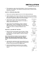
Observe the outside of the boat hull to find the areas that are 
mostly free from turbulent water. Avoid ribs, strakes, and other 
protrusions as these create turbulence (Figure 14). 


• 

As a general rule, the faster the boat can travel the further aft 
and closer to the centerline of the hull the transducer has to be 
located to remain in contact with the water at high speeds. 


Step Two - Test the Mounting Location 

 
There is no opportunity for adjustment after the transducer glued 
in place. Therefore, it is best to perform a trial installation on inside the hull transducers 
first, and run the boat at high speeds to determine the best mounting area. 


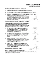
1.  At the identified mounting location, lay the transducer body face down with the 

pointed end towards the bow.


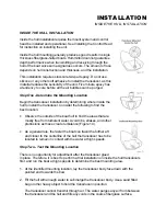
2.  Fill the hull with enough water to submerge the transducer body. Use a sand filled 

bag or other heavy object to hold the transducer in position. 


The transducer cannot transmit through air. The water purges any air from between 
the transducer and the hull and fills any voids in the coarse fiberglass surface. 


Summary of Contents for Wide Vision

Page 1: ......

Page 2: ...our number listed in the Customer Support section INSTALLATION OVERVIEW Your Humminbird fishfinder consists of two primary components to install the control head and the transducer The control head c...

Page 3: ...should the boat strike debris in the water or when trailering As an alternative to transom mounting it is possible on many fiberglass hulled boats to glue the transducer on the inside of the boat hull...

Page 4: ...other surface Trolling Motor Mounting The standard transducer can also be adapted to mount on most trolling motors using a different accessory kit This accessory includes a bracket and hose clamp that...

Page 5: ...minbird fishfinder The installation guide included on the next few pages provides detailed step by step instructions for installation of the control head and transducer For transom mount transducer in...

Page 6: ...the propeller s This turbulent water is normally confined to areas immediately aft of ribs strakes or rows of rivets on the bottom of the boat and in the immediate area of the propeller s Figure 1 On...

Page 7: ...g a 5 32 4mm bit drill the two holes to a depth of approximately 1 3cm On fiberglass hulls it is best to start with a smaller bit and use progressively larger drill bits to reduce the chance of chippi...

Page 8: ...ation after high speed testing 1 First adjust the pivot angle of the transducer body so its length is parallel with the length of hull of the boat Then pivot the transducer down so the rear is about 1...

Page 9: ...erference If the cable is too short extension cables are available to extend the transducer cable up to a total of 50 15 m Call Humminbird Customer Support for more information Follow these steps to r...

Page 10: ...hull to install the transducer Consider the following to find the best location Observe the outside of the boat hull to find the areas that are mostly free from turbulent water Avoid ribs strakes and...

Page 11: ...dry the mounting surface If the surface is excessively rough it may be necessary to sand the area to provide a smooth mounting surface Ensure the mounting area is clear and dry 3 Mix an ample quantit...

Page 12: ...y supported to protect the fishfinder from excessive wave shock and vibration and provide visibility while in operation The mounting area should allow sufficient room for the unit to pivot and swivel...

Page 13: ...holes Figure 22 Note if the cables must pass through the mounting surface at a different location drill the 1 25mm hole at that location and pass the cables through from underneath Also you must break...

Page 14: ...ll the excess cable from beneath the mounting surface so the connector holder aligns with the mounting holes on the front of the mounting bracket Figure 27 3 Snap the support plate to the rear of the...

Page 15: ...rmal operation unless you choose another option If you do not press any button before the timer reaches 0 the normal operation screen is displayed If the boat is in water sonar data appears If the bot...

Page 16: ...nce free water at higher boat speeds All Humminbird depthsounders are designed to work at speeds of 70 MPH or more however use caution when operating any boat at high speed High speed testing does not...

Page 17: ...actually on the water To exit the simulator press POWER to turn the unit off Pressing POWER again will power up the unit for normal operation When in simulator operation the Wide Vision unit will res...

Page 18: ...display for the terrain and target presentation The number of vertical pixels picture elements or dots in a given depth range determines the display resolution or ability to differentiate targets clo...

Page 19: ...comparing relative density as well as depth The transmitted sonar signal travels downward and is reflected back toward the surface by the bottom or other objects for display on screen The signal does...

Page 20: ...again The digital bottom depth will continue to update as usual even if the display is stopped LIGHT enables a two level display backlight and backlit keypad Pressing once will turn the light on low p...

Page 21: ...e may dictate the use of only one element however the Wide Vision is designed to gather maximum information when both narrow and wide elements are used simultaneously Dual Pressing ENTER will display...

Page 22: ...larity In murky water full of debris the Wide Vision will select a lower sensitivity setting In clear water where there is little debris to defract the sonar signal the sensitivity is set higher The S...

Page 23: ...is displayed at the bottom 1 3 of the display This leaves the top 2 3 to display anything between the surface and the bottom As your boat moves over deeper or shallower water the unit adjusts the dept...

Page 24: ...y to separate targets close together is enhanced The zoom range is determined by the depth range in use when Zoom is enabled In shallow water when the 15 or 30 depth range is used the zoom range will...

Page 25: ...tom Alarm The Wide Vision contains an audible alarm to warn you of shallow water depths This alarm is adjustable from 2 to 99 of depth To enable the alarm simply adjust the alarm depth using the UP an...

Page 26: ...is portrayed as a fish symbol The strength of the reflected sonar signal from a target is a good indicator of the size of the target and the fish symbol displayed represents the strength of the signa...

Page 27: ...nformation as it is received Advanced users may prefer this type of presentation so they can make there own interpretation from the information displayed TripLog TripLog provides a time distance calcu...

Page 28: ...display There are five rate settings available The default setting is rate 4 you may speed up or slow down the update rate to match your personal preference To present the most accurate representation...

Page 29: ...y of the changes that occur when Advanced operating mode is selected The selection is made in the System Menu and affects the following The base screen layout is modified to maximize the display for t...

Page 30: ...place of the dual beam transducer or used in conjunction with a transducer switch so both transducers can be connected to the Wide Vision See the section on Installing the Wide Vision for additional i...

Page 31: ...now configured for Wide Side operation When you exit the System Options menu the view you will see on screen is shown above right Viewing both left and right sides simultaneously gives you an excelle...

Page 32: ...de Side mode and the menu will not be present The ID menu is not present in Wide Side mode Fish are displayed as three different size fish symbols there are no hollow fish symbols to give directional...

Reviews:

Related manuals for Wide Vision