background image


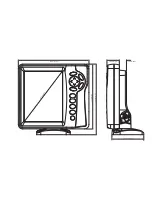
OTHER MOUNTING OPTIONS 
 
1.  The LCR gimbal bracket can also be mounted on the SM-4, quick disconnect swivel mount. 
2.  The LCR gimbal bracket can also be mounted directly to the dash without the swivel mount, 

however, this method is not recommended since the unit cannot be rotated.                                                                                                                                       


INSTALLING THE CABLES 
 
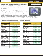
Your LCR comes equipped with Humminbird’s new Angle-Lock power and transducer 
connectors. The power connector is identified with the letter P on the back of the plug. 

Summary of Contents for LCR 3D

Page 1: ......

Page 2: ...uding aluminum Please carefully consider the following before installing your transducer TRANSDUCER MOUNTING OPTIONS A Transom Mount The Humminbird high speed transducer allows the transducer element...

Page 3: ...bronz thru hull transducer has a threaded stem which installs through a hole drilled in the boat hull leaving the housing exposed under the boat This type of installation must be used for many boats...

Page 4: ...use a silicone sealant between the screwhead and bracket in order to prevent leaking See Figure C Step 2 BRACKET INSTALLATION Fiberglass Boats If your boat has a stepped transom located below and und...

Page 5: ...cally in the three slots found in the bracket It is important to use a silicone sealant between the screwhead and bracket in order to prevent leaking Step 3 TRANSDUCER PIVOT ASSEMBLY Assemble the pivo...

Page 6: ...the bracket Slide the O ring on to the headed pin and insert it through the two parts Assemble by screwing the x3 8 allen head screw into the end of the pin and tighten See Figure G Step 5 ANGLE ALLIG...

Page 7: ...h this type installation it is important that the transducer be mounted by someone familiar with the use of two part epoxy adhesives For this reason Techsonic Industries Inc will not be responsible fo...

Page 8: ...ye of the transducer The bubbles will disappear in a short time or can be removed by rubbing the transducer eye with your fingers while the transducer is in the water 4 If your instrument should fail...

Page 9: ...Install the mounting knobs and tighten snugly The unit can now be swiveled and tilted to any desired position...

Page 10: ...cket can also be mounted directly to the dash without the swivel mount however this method is not recommended since the unit cannot be rotated INSTALLING THE CABLES Your LCR comes equipped with Hummin...

Page 11: ...ole cover after determining the necessary wire length from the hole The power cable has a red lead to the positive post and the black lead to the negative post Install a 1 amp fuse between the red cab...

Page 12: ...centered within a signal from being displayed on screen as large fish This also applies to large fish that might otherwise have been passed off as bait fish or not seen at all when they were located o...

Page 13: ...manually adjust contrast as described in this manual Though it includes sophisticated electronics the LCR 3D is tough enough to take the pounding punishment of rough seas or a race across the lake Com...

Page 14: ...pen 12 volt DC power source your boat s battery 1 amp fuse CABLE CONNECTIONS The back of the LCR 3D has a connector for power input labeled 1 and sensor input labeled 2 The power and sensor cables sup...

Page 15: ...essories enhance the performance and capabilities of your LCR 3D and can be added at any time For more information on these accessories contact your local Humminbird dealer or call our toll free Custo...

Page 16: ...cur see Troubleshooting later in this manual for tips from the Humminbird engineers If you don t find the solution there call our toll free Customer Service Hotline and speak with one of our highly tr...

Page 17: ...tual use especially in familiar waters If you know what s below and see it on screen you ll quickly become a LCR 3D expert The LCR 3D offers function selection with front panel buttons Note that to se...

Page 18: ...e three different ways to view the sonar information each is accessed by pressing the VIEW button The 3D view is what you see when you first power the unit up and provides a detailed three dimensional...

Page 19: ...rs the additional benefit of individual beam selection Each of the four sonar beams may be viewed independently or all four beams may be combined into one view This unique beam control allows you to p...

Page 20: ...sh Structure or thermoclines are shown with individual pixels or groups of pixels ID ties the fish to the bottom beneath it for location in the 3D view A Word About Fish Size The size of the fish symb...

Page 21: ...he area of the display beneath the bottom is blacked in to help better visualize the underwater view Turning ID off provides the raw sonar information and lets you do the interpretation In the Quad Be...

Page 22: ...ng 0 Digital Filter On The LCR 3D automatically adjusts to the proper amount of sensitivity for conditions i e depth You can bias the setting or 5 levels to suit your personal taste Increasing the sen...

Page 23: ...shows a flat grid if the bottom is below the depth you have set In the 2D view the bottom will simply not be seen on screen 3 Enabling Bottom Alarm Factory setting OFF The Bottom Alarm lets you speci...

Page 24: ...ow fish don t appear larger than deeper fish 5 Using Zoom Factory Setting OFF Zoom provides a detailed view of a portion of the screen image and can be used in any view The zoom range or area to be en...

Page 25: ...selected you can use the ENTER button to switch Bottom Lock on and off without having to press SELECT first 7 Adjusting Custom Program Factory Settings Display Speed 8 Contrast 8 Perspective Left Uni...

Page 26: ...arge area of the return is the bottom Any deviations in the area between the two are fish or other targets not attached to the bottom The horizontal width of the bottom return represents the strength...

Page 27: ...likely in the sensor or the LCR 3D itself Operating Frequency 455 KHz Power Requirement 10 16 VDC Power Cable Length 48 Sensor standard SHS 9 Sensor Cone Angle 45 degrees side to side 16 degrees front...

Reviews: