background image

34

Main Menu

Main Menu

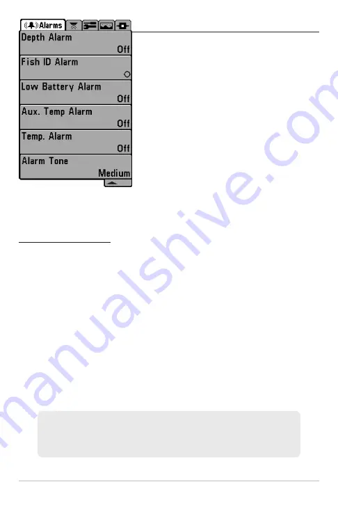
The  Main  Menu  provides  the  standard  set  of
menu  options,  including  the  settings  that  are
changed  less  frequently.  The  Main  Menu  is
organized under the following tabs to help you
find  a  specific  menu  item  quickly:  Alarms,
Sonar, Setup, Views, and Accessories. 

NOTE:

Menu options can be expanded or simplified by

setting  the  User  Mode  to  Advanced  or  Normal.  See

Main Menu: User Mode

for details.

To use the Main Menu:

1. In any view, press the MENU key twice. 

2. Press the RIGHT or LEFT Cursor keys to highlight a menu tab.

3. Press  the  UP  or  DOWN  Cursor  keys  to  select  a  specific  menu  option

under that tab. 

4. Press the RIGHT or LEFT Cursor keys again to change a menu setting. 

A  down  arrow  at  the  bottom  of  a  menu  means  that  you  can  scroll  to
additional menu options using the DOWN Cursor key. 

A right or left arrow on a menu option means that you can use the RIGHT
or LEFT Cursor keys to make changes or to see more information.

Press the EXIT key to move quickly to the top of the tab.

Main Menu (Normal User Mode)

Total Screen Update -

When you change any menu settings that affect the

current view, the view will update immediately (i.e. you don’t have to exit the
menu to apply the change to the screen). 

Summary of Contents for 748 3D

Page 1: ...531879 1EN_A 748 3D Operations Manual ...

Page 2: ...d only be performed by authorized service personnel Any modification of the serial number or attempt to repair the original equipment or accessories by unauthorized individuals will void the warranty WARNING This product contains chemicals known to the State of California to cause cancer and or reproductive harm WARNING Do not travel at high speed with the unit cover installed Remove the unit cove...

Page 3: ...member state requirements please contact your dealer or distributor from which your product was purchased ROHS STATEMENT Product designed and intended as a fixed installation or part of a system in a vessel may be considered beyond the scope of Directive 2002 95 EC of the European Parliament and of the Council of 27 January 2003 on the restriction of the use of certain hazardous substances in elec...

Page 4: ...1 Freeze Frame and Active Cursor 11 Instant Image Update 11 Bottom Presentation 12 Views 14 3D Sonar View 16 2D Sonar View 18 2D 3D Sonar Combo View 19 6 Beam Sonar View 20 2D Zoom View 21 2D Big Digits View 22 What s on the 700 Series Control Head 23 Key Functions 24 POWER LIGHT Key 24 VIEW Key 25 MENU Key 25 4 WAY Cursor Control Key 25 EXIT Key 26 Accessory Bus 27 The Menu System 28 Table of Con...

Page 5: ...y 3D Sonar 3D 2D Sonar Combo Views only 39 2D Sonar Window 3D 2D Sonar Combo View only 40 Reset View 3D Sonar 3D 2D Sonar Combo Views only 40 6 Beam Sensitivity 6 Beam Sonar View only 40 Sensitivity 2D Sonar 2D Sonar Zoom 2D Big Digits Views only 41 Upper Range Advanced 2D Sonar 2D Big Digits Views only 42 Lower Range 2D Sonar 2D Sonar Zoom 2D Big Digits Views only 42 Chart Speed 2D Sonar 2D Sonar...

Page 6: ... Noise Filter Advanced 54 Max Depth Advanced 2D Sonar Views only 54 Water Type Advanced 54 Setup Menu Tab 55 Units Depth 56 Units Temp International only 56 Units Distance with Temp Speed or GPS Receiver 56 Units Speed with Temp Speed or GPS Receiver 56 User Mode 57 Language International only 57 Triplog Reset with Temp Speed or GPS Receiver 57 Restore Defaults 57 Select Readouts Advanced 2D Sonar...

Page 7: ...st of authorized international distributors please visit our Web site at humminbird com or contact our Customer Resource Center at 334 687 6613 NOTE Entries in this Table of Contents which list with Temp Speed only require the purchase of separate accessories You can visit our Web site at humminbird com to order these accessories online or contact our Customer Resource Center at 1 800 633 1468 NOT...

Page 8: ......

Page 9: ...here isn t a transducer attached to the control head NOTE See Start Up Options Menu for more information If a functioning transducer is connected Normal operation will be selected automatically at power up and your Fishing System can be used on the water If a transducer is not connected and you wait too long to select a Start Up Option the system will default to whichever menu is already highlight...

Page 10: ...ocation size and composition of an object Sonar is very fast A sound wave can travel from the surface to a depth of 240 ft 70 m and back again in less than 1 4 of a second It is unlikely that your boat can outrun this sonar signal SONAR is an acronym for SOund and NAvigation Ranging Sonar uses precision sound pulses or pings which are emitted into the water in a teardrop shaped beam The sound puls...

Page 11: ...lance between depth performance and resolution Low frequencies 83 kHz are typically used to achieve greater depth capability The power output is the amount of energy generated by the sonar transmitter It is commonly measured using two methods Root Mean Square RMS measures power output over the entire transmit cycle Peak to Peak PtP measures power output at the highest points The benefits of increa...

Page 12: ...narrow beams together gives you a wide area of coverage for terrain interpretation and fish location without sacrificing the detail only a narrow beam can provide Your Fishing System gathers information from a continuous series of these returned signals It then interprets this information to create a detailed 3 dimensional view of the terrain passing beneath your boat as you travel across the wate...

Page 13: ...ntage of providing increased sonar resolution but is limited to a depth capability of 240 ft 75 m The 83 kHz single beam sonar has the advantage of providing sonar information to 1000 ft 330 m but provides less resolution than the 455 kHz beam NOTE Depth capability is affected by such factors as boat speed wave action bottom hardness water conditions and transducer installation How Sonar Works ...

Page 14: ...Triplog of nautical or statute miles traveled BottomContour Showstheshapeofthe bottom derived from depth measurements on 6 beams 3 bottom styles are available the front edges of the bottom contour are outlined to create a visual anchor The width of the bottom covered is approximately equal to the depth Temperature Water surface temperature Depth Water depth can be set to alarm when the water becom...

Page 15: ...indicate fish off the starboard side Each fish icon is available in three different sizes Larger fish icons are used to represent stronger returns The icons used in the 2D Sonar View are identical to the icons used in the 3D Sonar View Boat Direction Arrow A simple solid 3D boat is drawn when the Upper Depth Range is 0 A solid 3D arrow is drawn when the Upper Depth Range is not 0 Upper and Lower D...

Page 16: ...th Temp Speed Accessory Distance Distance traveled with Temp Speed Accessory Average Speed Average speed reading with Temp Speed Accessory Second Sonar Return When the sonar signal bouncesbetweenthebottomandthesurfaceofthe water and back again Use the appearance of the second return to determine bottom hardness Hard bottomswillshowastrongsecondreturn whilesoft bottomswillshowaveryweakoneornoneatal...

Page 17: ...ed When a target is detected a Fish ID symbol appears on the display with the depth displayed above it The size of the symbol indicates the intensity of the sonar return The unit will clearly show schools of Bait Fish as clouds of different shapes and sizes depending on the number of fish and boat speed Battery Voltage The voltage of the boat s battery It can be set to alarm if the voltage falls b...

Page 18: ...w appears on the right side of the display in the Sonar View only The RTS Window updates at the fastest rate possible for depth conditions and shows only the returns from the bottom structure and fish that are within the transducer beam The RTS Window plots the depth and intensity of a sonar return see Sonar Menu Tab RTS Window The Narrow RTS Window indicates the sonar intensity through the use of...

Page 19: ...Press any arrow on the 4 WAY Cursor Control key and the screen will freeze and a cursor will be displayed Use the 4 WAY Cursor Control key to move the cursor over a sonar return and the depth of the sonar return will be displayed in the cursor dialog box NOTE In 2D Sonar Views the RTS Window continues to update in Freeze Frame To return to a scrolling display and exit Freeze Frame press the EXIT k...

Page 20: ...k appears as a thinner line across the display A Soft Bottom such as mud or sand appears as a thicker line across the display Rocky Bottoms have a broken random appearance The sonar returns from the bottom structure and fish can be represented as Inverse Structure ID WhiteLine or Black Bottom Black See Sonar X Press Menu Bottom View to set the Bottom View Bottom Contour Profile with RTS Window Har...

Page 21: ...s has the benefit of ensuring that strong returns will be clearly visible on the display WhiteLine highlights the strongest sonar returns in white resulting in a distinctive outline This has the benefit of clearly defining the bottom on the display Black Bottom Black displays all pixels below the bottom contour as black regardless of signal strength This has the benefit of providing a high contras...

Page 22: ...View will be the default view Cycle When you press the VIEW key repeatedly the display cycles through the available views on your screen When you press the EXIT key repeatedly the display cycles through the available views in reverse order Customize You can display or hide any view to suit your fishing preferences See the following pages for more information about each View Views ...

Page 23: ...y attached The digital readouts on the Sonar View can be customized See Setup Menu Tab Select Readouts for more information 1 Press the MENU key twice to access the tabbed Main Menu then press the RIGHT Cursor key until the Setup tab is selected 2 Press the DOWN Cursor key to highlight Select Readouts and press the RIGHT Cursor key to access the Select Readouts submenu NOTE If the Select Readouts ...

Page 24: ...is connected or if a GPS receiver is connected Location The location of your boat in relation to the on screen information is represented by the boat icon Sonar Returns The most recent sonar returns are charted on the upper right side of the screen and move to the lower left as new information is received The width of coverage is approximately equal to the depth Fish ID If a return meets certain c...

Page 25: ...view use the 4 WAY Cursor Control key to change the perspective Press the LEFT Cursor key to shift the viewpoint left and press the RIGHT Cursor key to shift it right Press the Up or Down Cursor keys to shift the point of view up or down 2 Reset Perspective Press the MENU key once and select Reset View from the X Press Menu 3D Sonar View Depth Upper Depth Range 3D Reference Frame Fish ID Symbols 3...

Page 26: ...change based on the Select Readouts settings or the optional purchase accessories attached see Setup Menu Tab Select Readouts Freeze Frame Use the 4 WAY Cursor Control key to freeze the display and move the cursor over a sonar return The depth of the sonar return will be displayed in the cursor dialog box NOTE If the Depth number is flashing it means that the unit is having trouble locating the bo...

Page 27: ...aneously viewing the 2D window for structure and bottom hardness Depth is always displayed in the upper left hand corner Digital Readouts in the 2D 3D Sonar Combo View cannot be customized which makes information such as water temperature and voltage unavailable in this view NOTE Refer to the 3D Sonar View and the 2D Sonar View sections for more information on these views 2D 3D Sonar Combo View De...

Page 28: ...View also provides information on sonar targets relative to the boat The far right window displays sonar targets which are to the far right of the boat and the far left window displays sonar targets which are to the far left of the boat The remaining windows display sonar targets which are successively closer to the boat The width of coverage is approximately equal to the current depth Digital Rea...

Page 29: ...he zoomed view updates automatically The Full Range View is displayed on the right side of the screen The Full Range View includes the Zoom Preview Box which shows where the zoomed view is in relation to the full range view The Upper and Lower Depth Range numbers indicate the high and low range of the water which is being viewed Sonar Zoom View Digital depth is displayed in the upper left hand cor...

Page 30: ...o the Fishing System NOTE The digital readouts in the Big Digits View cannot be customized The Triplog shows distance traveled average speed and time elapsed since the Triplog was last reset Big Digits View Depth Temperature Speed Timer shows the time elapsed since Triplog was last reset Distance is the distance traveled since the Triplog was last reset Voltage displays the battery voltage Average...

Page 31: ...asy to use A combination of keys and special features allows you to control what you see on the display Refer to the following illustration and see Key Functions for more information Screen 1 MENU key 4 EXIT key 5 2 3 4 5 1 POWER LIGHT key 6 VIEW key 2 4 WAY Cursor Control key LEFT RIGHT UP or DOWN Cursor keys 3 6 ...

Page 32: ...Up Options Menu Power Off Press and hold the POWER LIGHT key for 3 seconds A message will appear to indicate how many seconds there are until shutdown occurs To ensure that shutdown occurs properly and any menu settings will be saved your Fishing System should always be turned off using the POWER LIGHT key Adjust the Backlight or the Display Contrast Press the POWER LIGHT key to access the Light a...

Page 33: ...nu Press the MENU key twice in any view to access the Main Menu which is organized under tabbed headings to help you find a specific menu item quickly 4 WAY Cursor Control Key LEFT RIGHT UP or DOWN Cursor keys The 4 WAY Cursor Control key has multiple functions which depend on the situation as follows Menu Selection Press the UP or DOWN Cursor keys to highlight a menu option then press the RIGHT o...

Page 34: ...e EXIT key to exit the menu mode and return to the view If a menu is active press the EXIT key to return to the previous level in the menu system From any view press the EXIT key to cycle through the available views in reverse order If Freeze Frame is active press the EXIT key to return to a scrolling display If the Cursor is active press the EXIT key to remove the cursor from the display ...

Page 35: ...o the menu system automatically when an accessory is plugged into the unit In addition multiple accessories can be attached simultaneously See Accessories Menu Tab and 700 Series Fishing System Accessories in this manual as well as your accessory s operations manual for additional details NOTE Accessories to enable WeatherSense SmartCast Wireless Sonar Link and GPS functionality require separate p...

Page 36: ...ator System Status and PC Connect X Press Menu The X Press Menu provides a shortcut to the most frequently used settings and the options on the X Press Menu correspond with the current view Main Menu The Main Menu is a standard set of menu settings which are organized under the following tabbed headings Alarms Sonar Setup Views and Accessories NOTE The X Press Menu s and the Main Menu options can ...

Page 37: ...s described on the following pages Also see Power On for additional information Normal Use Normal for on the water operation with a transducer connected If a functioning transducer is connected Normal operation will be selected automatically at power up and your Fishing System can be used on the water To exit Normal operation power off your Fishing System ...

Page 38: ... for later use NOTE It is important to select Simulator manually from the Start Up Options Menu as opposed to letting the Fishing System enter Simulator automatically as it will if a transducer is not connected and you do nothing during power up A message will appear often on the display to indicate Simulator mode To exit Simulator power off your Fishing System System Status Use System Status to v...

Page 39: ... Circuit Board PCB serial number software revision total hours of operation and the input voltage Accessory Test lists the accessories connected to the system NOTE The speed accessory will be detected only if the paddlewheel has moved since your Fishing System was powered up Self Test Screen System Status Accessory Test Screen ...

Page 40: ...d com or contact our Customer Resource Center at 1 800 633 1468 Updating Software requires the following top level steps 1 Log on to humminbird com Register your Fishing System Download HumminbirdPC to your computer 2 From your Humminbird online account download the latest control head software to your computer 3 Follow the instructions included with the PC Connect cable to connect your Fishing Sy...

Page 41: ...IGHT or LEFT Cursor keys to change the menu setting NOTE The X Press Menu will collapse temporarily and the screen will update if it is affected by your menu setting change which allows you to see the effects of your change immediately 3 Reactivate the X Press Menu by pressing the UP or DOWN Cursor keys Total Screen Update When you change any menu settings that affect the current view the view wil...

Page 42: ...eys to highlight a menu tab 3 Press the UP or DOWN Cursor keys to select a specific menu option under that tab 4 Press the RIGHT or LEFT Cursor keys again to change a menu setting A down arrow at the bottom of a menu means that you can scroll to additional menu options using the DOWN Cursor key A right or left arrow on a menu option means that you can use the RIGHT or LEFT Cursor keys to make chan...

Page 43: ...or see more information If you press MENU or EXIT to leave the Main Menu and then return to the Main Menu at a later time the menu will open to the same tab as the last time the Main Menu was displayed Note for all Menu Settings The settings in all menus are adjusted in the same way Simply use the 4 WAY Cursor Control key to highlight a menu option and then change the settings or activate the opti...

Page 44: ... To change the User Mode setting 1 Press the MENU key twice to access the Main Menu 2 Press the RIGHT Cursor key until the Setup tab is selected 3 Press the DOWN Cursor key to highlight User Mode on the Setup main menu 4 Press the RIGHT or LEFT Cursor keys to change the User Mode setting Normal Advanced Default Normal NOTE Any changes made while in Advanced Mode will remain in effect after you swi...

Page 45: ...37 Main Menu Sonar Tab Advanced Mode Sonar Tab Normal Mode ...

Page 46: ...U key once while in any of the Sonar Views to access the Sonar X Press Menu NOTE Menu options will vary with the view 2D 3D 6 Beam 2D Zoom View or Combo View See Views for more information NOTE Menu options can be expanded or simplified by setting the Fishing System User Mode to Advanced or Normal See Main Menu User Mode for details Sonar X Press Menu ...

Page 47: ...h range into Manual mode 3D History 3D Sonar 3D 2D Sonar Combo Views only Settings Most 2 9 Least Default 6 3D History determines the speed at which the sonar information moves across the 3D display and consequently the amount of history shown A faster speed shows less history and is preferred by most anglers however the sonar information moves across the display quickly A slower speed keeps the i...

Page 48: ...he original view settings See Views for more information 6 Beam Sensitivity 6 Beam Sonar View only Settings Low 1 High 20 Default 10 6 Beam Sensitivity controls how much detail is shown on the display Increasing the sensitivity shows more sonar returns from small baitfish and suspended debris in the water however the display may become too cluttered When operating in very clear water or greater de...

Page 49: ...vity to see weaker returns that may be of interest If the sensitivity is adjusted too high the display may become too cluttered Decrease the sensitivity to eliminate the clutter from the display that is sometimes present in murky or muddy water If Sensitivity is adjusted too low the display may not show many sonar returns that could be fish NOTE The Sensitivity setting is a global setting and will...

Page 50: ...splayed in the lower right corner of the screen to indicate the unit is in Manual mode Adjust the Upper and Lower Range together to view a specific depth range especially when looking for fish or bottom structure NOTE A minimum distance of 10 feet will be maintained between the Upper and Lower Range regardless of the manual settings entered For example if you are only interested in the area betwee...

Page 51: ...e possible for the depth conditions Bottom View 2D Sonar 2D Sonar Zoom 2D Big Digits Views Only Settings Inverse Structure ID WhiteLine Bottom Black Default Structure ID Bottom View selects the method used to represent bottom and structure on the display See What s on the Sonar Display Bottom Presentation for more information Zoom Level 2D Zoom View only Settings 2x 4x 6x 8x Default 2x Zoom Level ...

Page 52: ...wice to access the Main Menu The Alarms tab will be the default selection NOTE When an alarm is triggered you can silence it by pressing any key The alarm will be silenced and will not be triggered again until a new instance of the alarm condition is detected Alarms Menu ...

Page 53: ...ll only sound if Fish ID is on For example if you ve set the Fish ID Alarm to sound for Large fish only the Fish ID alarm will sound when a large sized fish is detected Low Battery Alarm Settings Off 8 5V 13 5V Default Off Low Battery Alarm sounds when the input battery voltage is equal to or less than the menu setting The battery alarm will only sound for the battery that is connected to the Fish...

Page 54: ...ional Models only Alarm Tone Settings High Medium Low Default Medium Alarm Tone selects the pitch of the alarm sound A brief tone will be produced as you adjust the Alarm Tone so that you can select the tone that you can hear best For example if the Temp Alarm is set to 58 degrees Fahrenheit and the water temperature falls from 60 degrees to 58 degrees the Temp Alarm will sound Similarly if the wa...

Page 55: ...ey twice to access the Main Menu and then press the RIGHT Cursor key until the Sonar tab is selected NOTE Menu options can be expanded or simplified by setting the User Mode to Advanced or Normal See Main Menu User Mode for details Sonar Menu Advanced ...

Page 56: ... or 2D Beam Select sets which sonar returns from the transducer will be displayed on the screen When Beam Select is set to 455 kHz the returns from the 455 kHz narrow beams will be displayed in all views and the maximum depth capability of your unit will be 240 ft 75 m When the depth is greater than 240 ft 75 m Beam Select should be set to 83 kHz The unit will continue to acquire sonar returns bel...

Page 57: ...e to see only raw sonar returns on the display When Max Mode is selected you will see the maximum sonar information available within the transducer beam so more fish arches and better jig tracking are shown Choose Clear Mode to see less clutter and more fish size accuracy on the display When Clear Mode is selected the clutter is filtered and sonar returns are interpreted to provide more details ab...

Page 58: ...ing a fish Three different fish size icons represent the intensity of the sonar return and provide an indicator of relative fish size There is also a unique symbol set associated with each of the six beams for a total of 18 possible fish symbols which can be displayed The following graphic illustrates the different Fish ID symbols and shows the beams with which they are associated For instance a h...

Page 59: ... fish within the sonar beam greatly affect the shape of the arch Fish ID Sensitivity Settings Low 1 High 10 Default 5 Fish ID Sensitivity adjusts the threshold of the Fish ID detection algorithms Selecting a higher setting allows weaker returns to be displayed as fish This is useful for identifying smaller fish species or baitfish Selecting a lower setting displays fewer fish from weak sonar retur...

Page 60: ...rrow Off Default Wide RTS Window sets the RTS Window to either Wide or Narrow or turns it off in the 2D Sonar View The RTS Window always updates at the fastest rate possible and only displays returns that are within the transducer beam See What s on the 2D Sonar Display for more information NOTE The Wide RTS Window does not use grayscale Zoom Width 2D Zoom View only Settings Narrow Medium Wide Def...

Page 61: ... display additional weak returns and decreasing the 83 kHz Sensitivity will display fewer weak returns Depth Lines Advanced 2D Sonar Views only Settings Off On Default On Depth Lines divide the display into four equal sections which are separated by three horizontal depth lines The depth of each line is displayed along the depth scale You can turn Depth Lines On or Off Depth Lines Depth Lines ...

Page 62: ...et to Auto the Fishing System will acquire bottom readings as needed within the capacity of the unit When Max Depth is set to match your fishing maximum depth your Fishing System will not attempt to acquire sonar data below that depth so more detail will be shown on the screen NOTE If the bottom is deeper than the Max Depth setting the digital depth readout will flash indicating that the Fishing S...

Page 63: ... Menu then press the RIGHT Cursor key until the Setup tab is selected NOTE Menu options will vary depending on which accessories are attached to the unit NOTE Menu options can be expanded or simplified by setting the User Mode to Advanced or Normal See Main Menu User Mode for details Setup Menu Tab ...

Page 64: ...es International Models Meters Kilometers Meters Nautical Miles Feet Statute Miles Feet Nautical Miles Default Meters Kilometers Units Distance selects the units of measure for all distance related readouts and will appear in the menu if a Temp Speed Accessory is connected and the paddlewheel has moved at least once or if a GPS Receiver is connected Units Speed with Temp Speed or GPS Receiver Sett...

Page 65: ...eset with Temp Speed or GPS Receiver Settings Follow screen instructions to activate Triplog Reset resets the Triplog to zero and will appear in the menu if a Temp Speed Accessory is connected and the paddlewheel has moved at least once or if a GPS Receiver is connected The Triplog provides the following information timer for elapsed time distance traveled since last reset and average speed NOTE S...

Page 66: ...lect Off See Views to change the Select Readouts Data windows can display readouts from supported accessories such as Temp Speed Each data window can be empty or contain one of the following information categories Speed Temperature Triplog Voltage Select Readouts The readout position on the screen is shown in the Select Readouts Window NOTE The availability of the digital readout information corre...

Page 67: ...itive vertical measurement from the transducer to the waterline to read the depth from the waterline Enter a negative vertical measurement from the transducer to keel to read the depth from the keel Digits Format Advanced Settings Small tenths Large tenths No tenths Default Small tenths Digits Format adds a tenth decimal place to readouts such as Temperature and Depth The format can be changed to ...

Page 68: ... NMEA 0183 is a National Marine Electronics Association standard for data communication The following NMEA sentences are output DPT Depth MTW Water Temperature GLL Lat Lon Position GGA GPS Fix Data RMC Recommended Minimum Specific GNSS Data VTG Course Over Ground and Ground Speed ZDA Time and Date When navigating the following NMEA sentences are also output APB Autopilot Sentence B BWR Bearing and...

Page 69: ...n Settings Off Visible Default Visible Demonstration controls whether the Demonstration Mode is visible or off The Demonstration Mode appears on the screen if you don t press any keys during the warning screen at power up Menu settings cannot be saved in Demonstration see Power On and Start Up Options Menu Sound Control Settings No Sounds Alarms Only All Sounds Default All Sounds Sound Control all...

Page 70: ...ursor key until the Views tab is selected This menu tab allows you to set the available views to either hidden or visible in the view rotation The view will be removed from the view rotation if it is set to Hidden and will be displayed in the view rotation if it is set to Visible NOTE See Views for more information Views Menu ...

Page 71: ...hat support the accessory will be added automatically See your accessory s operations manual for detailed information NOTE Accessories to enable WeatherSense and the SmartCast Wireless Sonar Link require separate purchases You can visit our Web site at humminbird com or contact our Customer Resource Center at 1 800 633 1468 for additional details Accessories Menu Tab no accessories attached Access...

Page 72: ...ving corrosion from the battery terminals or wiring or actually replacing the battery if necessary Fishing System Defaults to Simulator with a Transducer Attached A connected and functioning transducer will cause the newly started Fishing System to go into Normal operating mode automatically If when you power up the Fishing System it goes into Simulator mode automatically even though a transducer ...

Page 73: ...djusted A mix of air and water flowing around the transducer cavitation may be interfering with the interpretation of sonar data See your Installation Guide for suggestions on adjusting the transducer position Electrical noise from the boat s engine may be interfering with sonar reception See Finding the Cause of Noise for more information Sonar readings may be affected if the transducer is not po...

Page 74: ...noise re appears To determine whether the boat s engine is the source of the noise increase the RPMs while the boat is in neutral and stationary to see if the noise increases proportionately if noise appears when you rev the engine the problem could be the spark plugs alternator or tachometer wiring Replace the spark plugs with resistor plugs install an alternator filter or route the control head ...

Page 75: ...ur Fishing System to access advanced FishingGPS trackplotter and navigation capabilities built in to your Fishing System GPS Connection Cable Purchase the GPS Connection Cable in order to connect a handheld or other NMEA GPS compatible device that you may already own to your Fishing System Wireless Sonar Link WSL Purchase the Wireless Sonar Link WSL accessory to receive remote sonar signals from a...

Page 76: ...3 5 mm Power Requirement 10 20 VDC LCD 640 V x 320 H Transducer SHS 7W Transducer Cable Length 20 ft 6 m Current Draw 615 mA IPX Rating IP67 Waterproof Submersible 1 m for 30 minutes and dust tight NOTE Humminbird verifies maximum stated depth in saltwater conditions but actual depth performance may vary due to transducer installation water type thermal layers bottom composition and slope NOTE Pro...

Page 77: ...le in the sonar beam Precision sonar beams such as the Humminbird 20 beam have a smaller dead zone than wider sonar beams Decibel The measurement for sound pressure level or intensity of the sonar return See dB Down Point dB Down Point The standard decibel level at which the sonar cone angle is measured and is written as 10 dB or 3 dB Measurements at smaller down points bigger negative numbers ind...

Page 78: ... Peak measurement systems Either method is acceptable but it is important when comparing power outputs to make sure that the same measurement system is being used for both outputs because P T P numbers are 8 times higher than RMS numbers Greater power output allows the sonar signal to penetrate through weeds and thermoclines reach deeper depths and operate more effectively in noisy environments su...

Page 79: ...eed Through Water is provided by a speed paddlewheel and is the measurement of the flow past the boat which may vary depending on current speed and direction Speed Through Water is most critical for anglers using downriggers as it impacts the running depth of the down riggers Speed Over Ground is optimal for navigation as accurate destination times can be derived from this measurement Humminbird p...

Page 80: ...electrical energy from the transmitter into sound energy and that forms the sonar beam in turn Internally the transducer consists of one or more piezo electric disks that expand by very minute amounts to create the sound wave This element also works in reverse converting the returned sound energy back into an electrical signal that the receiver interprets See SONAR Zoom A feature that focuses on a...

Page 81: ...g ways By Telephone Monday Friday 8 00 a m to 4 30 p m Central Standard Time 1 800 633 1468 By e mail typically we respond to your e mail within three business days service humminbird com For direct shipping our address is Humminbird Service Department 678 Humminbird Lane Eufaula AL 36027 USA ...

Reviews: