020-9905 User Manual Q3 (Advanced 3 year old child) Rev G Page 22 of 82
© 2016 Humanetics Innovative Solutions
4.2 Head
Construction
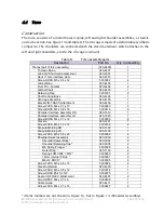
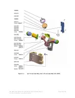
The head assembly consists of the following parts (see also Figure 10):
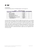
Table 6.
Head assembly parts
Description
Part No.
Qty. in Assembly
Head Assembly
020-1100
1
Head front assembly
020-1020
1
Head rear assembly.
020-1025
1
Screws BHCS M5 x 12
5000565
4
Load Cell structural replacement
020-2007
1
Screw FHCS M5 x 10
5000084
4
Accelerometer mounting base (standard)
020-1013A
1
Screw SHCS M3 x 40
5000649
1
Screw SHCS M3 x 10
5000119
2
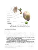
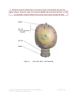
The head consists of two parts: the front assembly (skull and skin) and a rear assembly
(skull cap). The rear assembly may be removed by unscrewing the four M5x12 button
head cap screws located at the rear of the head. The head skin and skull are molded
together and cannot be separated. Inside the head is a large cavity which may be used to
mount various types of instrumentation. The standard arrangement is to have the head
mounting block bolted in the head which will accept 3 uni-axial accelerometers.
Optionally a bracket for combined accelerometer-angular rate sensor application (020-
1014) can be used.

