background image

10

The Below Deck Unit BDU

The Thuraya Mobility (Land Mobile) kit is shipped with the following contents:

Model

Hughes part 

number

Description

Thuraya  IP Voyager 

(9105) Land Mobile kit

3500462-0004

Radio, Thuraya IP Voyager (kit)

9506197-0001

WLAN antenna (2.4 GHz, 3 dB)

3500472-0001

Power cable with 3-pin connector

3500860-0001

SIM cover plate

9504275-0008

15 Amp, fast blow, ATO blade fuse (2 pieces)

PDF

Install Manual

PDF

User Manual

3500855-0001

Land Mobile Antenna Type HN221

TNC-TNC/6m

RF coax cable TNC-TNC (6 meter)

Table 1. Land Mobile Kit Parts

Below Deck Unit (BDU)

The BDU provides all of the TE interfaces, plus the interface for the antenna (ADU)

and manages the communications over the Thuraya network. Communication to the 

ADU is provided by a single RF cable from the BDU.

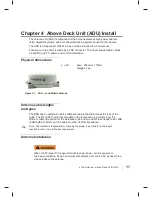
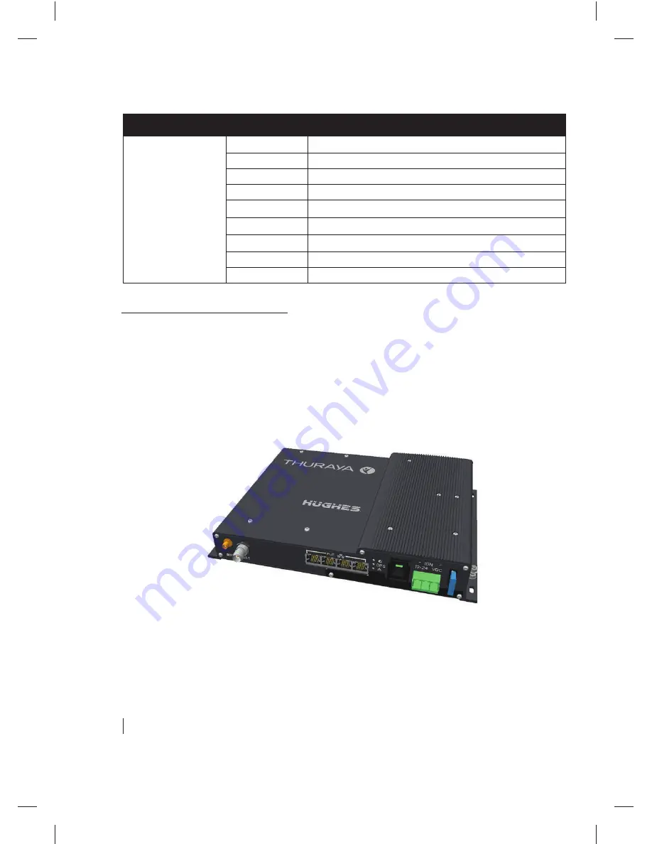
Physical dimensions

BDU:

Size:  46mm x 281mm x 233mm

Weight:  2.2kg

Figure 1-2. Below Decks Unit (BDU)

Summary of Contents for IP Voyager

Page 1: ......

Page 2: ...ort to ensure the correctness and completeness of the material in this document Hughes Network Systems LLC shall not be liable for errors contained herein The information in this document is subject to change without notice Hughes Network Systems LLC makes no warranty of any kind with regard to this material including but not limited to the implied warranties of merchantability and fitness for a p...

Page 3: ...5 Ethernet with Power over Ethernet PoE ports 11 WLAN port 12 Antenna port 12 SIM card 12 System power requirements 13 Table 4 System power requirements 13 Fuse 13 Chapter 2 Below Deck Unit BDU Install 15 Basic BDU installation procedure 15 Installation notes 15 BDU mounting information 16 Chapter 3 Above Deck Unit ADU Install 17 Physical dimensions 17 Antenna cable lengths and types 17 Antenna In...

Page 4: ......

Page 5: ...DU 10 Figure 1 3 Fitting the SIM card Cover 13 Figure 2 1 BDU mounting dimensions in mm 16 Figure 2 2 BDU Wiring Diagram 16 Figure 3 1 ADU Land Mobile Antenna 17 Tables Table 1 Land Mobile Kit Parts 10 Table 2 Power port pin out 11 Table 3 RJ 45 Ethernet port pinout 11 Table 4 System power requirements 13 ...

Page 6: ......

Page 7: ... personal injury or in some cases death as explained below Each of these signal words indicates the severity of the potential hazard WARNING indicates a potentially hazardous situation which if not avoided could result in death or serious injury CAUTION indicates a potentially hazardous situation which if not avoided could result in minor or moderate injury Safety symbols The generic safety alert ...

Page 8: ......

Page 9: ...amages resulting in the failure to conform to the instructions found herein as well as standard installation practices will be the responsibility of the installer Thuraya IP Voyager satellite terminals The Thuraya IP Voyager satellite terminal is composed of four core component parts the transceiver or Below Deck Unit BDU the antenna or Above Deck Unit ADU the power connector cable and an RF cable...

Page 10: ...plate 9504275 0008 15 Amp fast blow ATO blade fuse 2 pieces PDF Install Manual PDF User Manual 3500855 0001 Land Mobile Antenna Type HN221 TNC TNC 6m RF coax cable TNC TNC 6 meter Table 1 Land Mobile Kit Parts Below Deck Unit BDU The BDU provides all of the TE interfaces plus the interface for the antenna ADU and manages the communications over the Thuraya network Communication to the ADU is provi...

Page 11: ...t through connection to a PC with a standard Ethernet cable Table 3 shows the pinout of the Ethernet connector Pin 1 RX 2 RX 3 TX 4 NC 5 NC 6 TX 7 NC 8 NC Table 3 RJ 45 Ethernet port pinout Note The 48V and 48V are supplied over the TX RX pairs They are only active when an 802 3af compliant device is plugged in The other pairs 4 5 7 and 8 are unused The total power supplied by the PoE is limited t...

Page 12: ...power do not connect or disconnect the antenna cable while the unit is powered on ONLY use the Thuraya Land Mobile Antenna Type HN221 with this BDU use of other antennas may damage the BDU and Antenna and shall void the warranty SIM card SIM Card The BDU requires a Thuraya SIM to be installed Insert the SIM supplied by your service provider into the SIM card holder with the metal contacts facing d...

Page 13: ...installed part is from Littelfuse part number 0287015 To replace the fuse pull fuse out of fuse holder pliers may be needed to grip fuse and press new fuse into fuse holder Spare fuses are provided with your Thuraya IP Voyager terminal Power Cable The Power cable uses a Phoenix contact 1718384 PC5 3 STCL 7 62 connector and the pinout is shown in the Table below Color Function Red DC White Ignition...

Page 14: ...uch as accessory line or fuse block Extended use of ignition sense in the accessory position ACC by the end user may lead to a discharged car battery Note Ensure that the connection is a switched source OFF when ignition is off or in start and ON only when ignition switch is in the ACCESSORIES or RUN position Note If using the optional car adapter plug the ignition sense wire is already connected ...

Page 15: ... of wire for both Positive and Negative wires to ensure a minimal voltage drop under load Suggested wire size 14 AWG up to 8m 26ft 12 AWG up to 12m 40ft 10 AWG up to 20m 65ft 2 The remote switch line may be used to power the system up and down remotely It should be connected to a physical remote on off switch or the vehicle s ignition line When the engine is not running prolonged operation should ...

Page 16: ... around top and sides to provide adequate cooling 3 Mount the terminal onto a flat surface using at least four screws or bolts not supplied Use screws or bolts with a diameter between 3 5 to 4mm Vibration resistant screws or lock washers should be used Figure 2 1 BDU mounting dimensions in mm Figure 2 2 BDU Wiring Diagram Dimension BETWEEN Mounting Holes 271mm Dimen sion BETW EEN Mount ing Holes 1...

Page 17: ...ADU Land Mobile Antenna Antenna cable lengths and types The BDU has an automatic cable calibration feature that determines the loss of the cable The RF cable that comes standard in the terminal kit is 6 meters long If a different cable is required for the installation the end to end RF loss needs to be 10dB 0dB 8dB at 1 6GHz and the cable must be 50 Ohm impedance Note The installer is responsible ...

Page 18: ...ored beyond this distance Do not locate the antenna close to interfering signal sources or receivers It is recommended that no other antennas be located within three meters of the Thuraya Mobility antenna If there is other equipment installed near the Thuraya IP Voyager terminal it is recommended to operate all equipment simultaneously and verify there is no co interference It is important for the...

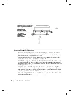
Page 19: ...a non tilting surface but may require individual length adjustment if the surface is tilting The M5 stainless steel bolts will have identical length if the three spacers are identical and may require individual length adjustment if spacer length are different Note 1 Drainage of the antenna a simple mechanism in the form of three holes in the dome plastic enclosure bottom is used The holes are made...

Page 20: ...ntenna There are three legs on the antenna where the magnets are placed Note the position of the two rubber washers just below and above each antenna leg the stainless steel washer above the upper rubber washer and the protective nut on top Now place the antenna with magnets on the roof of the car When installing the antenna cable it is important to protect against moisture by using self amalgamat...

Page 21: ...ation 5 10Hz with amplitude 2 54 mm 10 15Hz with amplitude 0 76mm 15 25Hz with amplitude 0 40mm 25 33Hz with amplitude 0 23mm Note Vibration levels in a typical installation are usually much less than the above mentioned values It is however the responsibility of the installer to verify that the cited levels are not exceeded in any mode of operation of the vehicle In case of abnormal vibration typ...

Page 22: ......

Page 23: ......

Page 24: ......

Reviews: