Chapter 7 • Pointing the antenna
62
1037312-0001 Revision B
Understanding the DAPT
display
When connected properly, the DAPT initially displays the IFL
receive cable voltage on its LCD display, as shown in this
example (the actual voltage may vary):
Important: To see pointing values, as described below, you must
check the box labeled
Enable OPI Display
on the appropriate
installation software screen on the installer laptop computer.
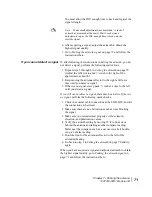
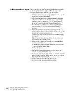
If the IDU is in receive pointing mode and you press the Advance
button (3), the display changes from IFL cable voltage to
COMM
Startup
and then (automatically) to
Mode
and
Value
:
The mode is either 0 or 2:
•
0 – Receive pointing.
•
2 – Automatic cross-pol (ACP), manual or automatic:
– Manual – The value is dynamic; it changes constantly.
– Automatic – The value is static; it does not change.
You cannot change the mode from the DAPT; you can only
change modes through the laptop.
In all modes the value is a relative indication of signal strength. A
higher number indicates a stronger signal.
OPI
The OPI, P/N 1031393-0002 (Figure 45) is a portable repeater
that displays signal strength values during antenna pointing.
Figure 45: Outdoor Pointing Interface (OPI)
Cable
connector
Display
Summary of Contents for AN6-098P
Page 6: ... Contents vi 1037312 0001 Revision B ...
Page 10: ... Tables x 1037312 0001 Revision B ...
Page 22: ...Chapter 1 Overview 6 1037312 0001 Revision B ...
Page 46: ...Chapter 3 Assembling the antenna 30 1037312 0001 Revision B ...
Page 58: ...Chapter 4 Installing a J type radio assembly 42 1037312 0001 Revision B ...
Page 72: ...Chapter 6 Cabling and connections 56 1037312 0001 Revision B ...
Page 92: ...Chapter 7 Pointing the antenna 76 1037312 0001 Revision B ...
Page 94: ... Acronyms and abbreviations 78 1037312 0001 Revision B ...


