background image

COMMUNICATION PORTS

RS485 COMMUNICATION PORT

The RS485 interface is used only for performing firmware updates directly for the BMS. This port 

cannot be used for any inverter communications. 

PLEASE NOTE: 


This port is reserved for administrative and workshop technicians.

RS232 COMMUNICATION PORT

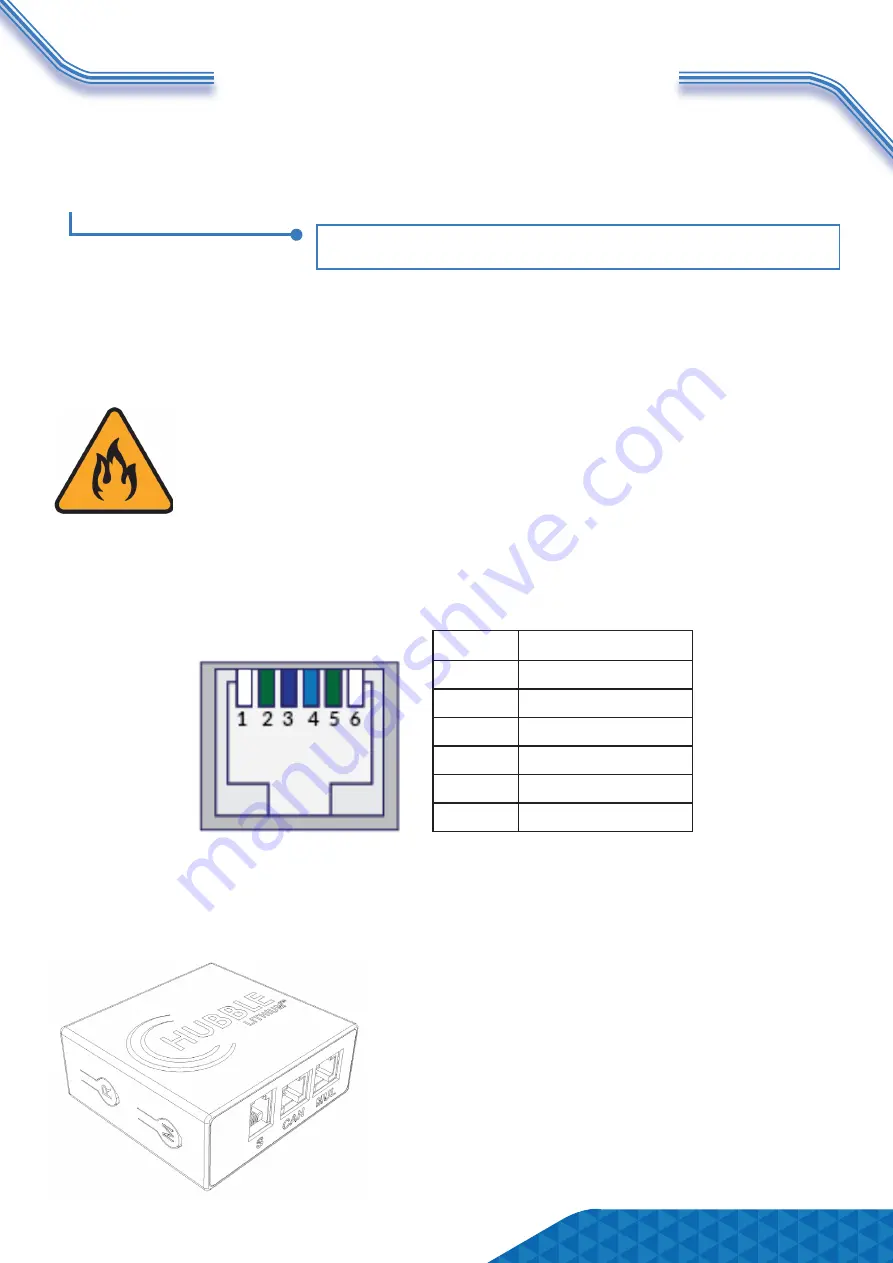
The RS232 interface is used to connect to either the Hubble Cloudlink device or for technical sup-

port to interface directly through a service laptop and access the BMS directly for programming 

and troubleshooting.

WARNING: FIRE HAZARD & WARRANTY VOID

DO NOT CONNECT THIRD PARTY DEVICE

It is strictly forbidden to access or interfere directly with the battery BMS through 

third party devices such as monitoring devices or logging devices that are not 

Hubble Lithium products. 

Third party monitoring and interfacing devices have the potential to change 

charge voltages and algorithms inadvertently - this can cause a catastroph-

ic  fire  hazard.  Therefore,  interfacing  to  the  BMS  directly  without  authorization  will 

void the warranty and Hubble Lithium will not be liable for any resulting damages. 

PIN

DEFINITION

1

-

2

GROUND

3

BMS TRANSMIT

4

BMS RECEIVE

5

GROUND

6

-

Page 4

ABOUT THE CLOUDLINK DEVICE

The Hubble Cloudlink is an optional add-on to the Hubble X and AM range of products. As long 

as the device is connected to Wi-Fi it will cloud, all battery and inverter data to our cloud-server, 

enabling users to remotely monitor their power system.

Learn more about the Hubble Cloudlink here:  

https://www.hubblelithium.co.za/hubble-cloudlink.html 


Access the latest Coudlink Setup Guide here: 

https://www.hubblelithium.co.za/cloudlink-setup.html

RS232 PIN LAYOUT:

Summary of Contents for AM-2

Page 1: ...verter and battery setup unless you are certain you understand the risk Speak to a qualified electrician if you are unsure V1 0 Please visit https www hubblelithium co za products html for the latest...

Page 2: ...ON 2 INVERTER SETUP PAGE 5 SECTION 3 LED INDICATORS PAGE 6 SECTION 4 BMS MAINTENANCE PAGE 7 SECTION 5 COMPLETING SETUP PAGE 8 INDEX Information published in this manual is correct as of the date publi...

Page 3: ...AM 2 WIRE DIAGRAM 1 Cover 2 Hanging Ear 3 Handle 4 Output Terminal 6 Cooling Case 7 Power Switch 8 Communication Interface 9 Reset Switch 10 LED Lights Page 1...

Page 4: ...etup and communication Each battery needs a unique serial address in order to communicate If you are only using one battery in your setup ensure you set the battery to Address 1 Page 2 DC ISOLATOR The...

Page 5: ...computer LAN cable to connect each battery The pin layouts for the ports are the same as the universal LAN cable WARNING PROTECTION MODE If your batteries are unbalanced or the voltage of each pack is...

Page 6: ...g devices that are not Hubble Lithium products Third party monitoring and interfacing devices have the potential to change charge voltages and algorithms inadvertently this can cause a catastroph ic f...

Page 7: ...sponding inverter guide https www hubblelithium co za The recommended cutoff is 44V 45V However the internal battery cutoff is as low as 40V Setting the cutoff to 40V will drain the battery to 0 For...

Page 8: ...D as standby Temperature Over current Fault Protection OFF ON OFF OFF OFF OFF DISCHARGE Normal Flash 3 OFF Indication by SOC Alarm Flash 3 Flash 3 Under Discharge Protection OFF OFF OFF OFF OFF OFF Te...

Page 9: ...acity charge discharge current temperature etc This can be downloaded by a service technician to help troubleshoot any issues or problems of the battery MAINTENANCE The Hubble BMS will protect the bat...

Page 10: ...etting up your system please contact our Technical Support Department via support hubblelithium co za Be sure to include the following information in your initial email so that we can provide you with...

Reviews: