PD1718
(Page 2)
Rev. 07/07
MAINTENANCE
Electrical and mechanical inspection of all components must be performed regularly. It is recommended
that inspection be performed monthly. Lubricate threads periodically.
• Inspect all contact wire terminals for tightness. Discoloration due to excessive heat is an indicator
of possible problems and should be thoroughly investigated and repaired as necessary.
• Check grounding and bonding for correct installation and secure connection.
• Check gaskets for deterioration.
• Clean exterior surfaces making sure nameplates remain legible.
• Inspect clamp guide assembly and cable grip tightness to ensure proper cable gripping.
• Inspect interior parts and replace those which are broken or excessively worn.
• Check all contacts for signs of excessive arcing or burning.
An Electrical Preventive Maintenance Program as described in the National Fire Protection Association
Bulletin NFPA No. 70B is recommended in addition to these required maintenance procedures.
Electrical power supply MUST BE OFF before and during installation or maintenance.
DISCONNECT primary power source and LOCK OUT. Installation and maintenance
procedure must be performed by a trained and competent electrician.
CAUTION
If any parts of the plug, receptacle or connector appear to be missing, broken or show
signs of damage, DISCONTINUE USE IMMEDIATELY! Do not modify these devices in any
way. Replace with new device. Failure to do so could cause serious personal injury and/or
equipment damage.
WARNING
POWER
CABLE
PLASTIC
SHEATH
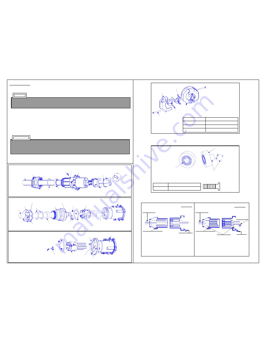
FIGURE 1 • CONNECTOR- Reverse Service
FIGURE 2 • PLUG-Reverse Service
FIGURE 3 • INLET-Reverse Service
STYLE 1
units ground the portable device and the
connector via the grounding conductor and the
plug shroud to the inlet detent spring clips and
housing. The inlet is grounded by virtue of its be-
ing an integral part of the conduit system. All con-
tacts are current carrying.
STYLE 2
units have an extra (grounding) contact which
forms a parallel circuit with the circuit formed by the
shroud and inlet detent spring clips.
FIGURE 6
STYLE 1
STYLE 2
INLET
CONNECTOR
Portable Cable
4-Conductor
Grounding
thru conduit
system
Factory installed
grounding strap
4th grounding)
wire, if desired
INLET
CONNECTOR
Portable Cable
4-Conductor
Grounding thru
conduit system
Equipment grounding
connected to plug shell
Equipment grounding
connected to plug shell
CABLE DIAMETER RANGE FOR 200 AMP
PLUGS & CABLE CONNECTORS
AMPERES
200
CABLE DIA. RANGE (IN.)
1.00-2.50
“Inner
Layers”
”SOLID” Side
“Inner Layer”
Pushed
Thru and Removed
Cable Gaging Strip
UseTo Determine
How Many “Inner
Layers” Are To
REMAIN
.
FIGURE 5
INSERT TO USE
Small & Large
Large Only
Neither
CABLE DIA. RANGE (IN.)
1.00-1.50
1.50-2.00
2.00-2.50
Clamp Screw
Clamp
Clamp Insert - Small
Clamp Insert - Large
Clamp Guide
FIGURE 4
(11)
(5)
(8)
(2)
(6)
(13)
(7)
POWER
CABLE
(12)
(17)
(16)
(15)
(14)
GROUND
TERMINAL
(STYLE 1 ONLY)
PLASTIC
SHEATH
(4)
PLASTIC
SHEATH
(18)
(20)
(19)
(16)
(2)
(15)
(14)
(6)
(11)
(5)
(4)
(9)
(7)
(8)
(1)
(2)
(3)
(12)


