Pub. 42004-561A
400-005 and 400-006 RigCom Stations
Page 9 of 16
P:\Standard IOMs - Current Release\42004 Instr. Manuals\42004-561A.docx
04/22
TB4
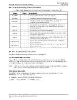
—Audio and Low Voltage Control Terminal Block
Table 4. Audio Signal and Low Voltage Control Connections at Terminal Block TB4
Name
Pin No.
Description
A
UX
M
IC
+
1
Positive terminal for the auxiliary microphone.
A
UX
M
IC
–
2
Negative terminal for the auxiliary microphone.
E
XT
C
ONT
+
3
Talk/listen control signal for Master/Slave operation. No
connection in Common Line mode.
E
XT
C
ONT
–
4
Ground reference for talk/listen control signal for Master/Slave
operation. No connection in Common Line mode or UNBAL
audio configuration.
S
HIELD
5
Ground reference for shield terminations.
A
UDIO
+
6
Positive side of the audio port line during 600-ohm or 15-kilohm
termination configuration.
A
UDIO
–
7
Negative side of the audio page port line during 600-ohm or 15-
kilohm termination configuration.
F
OOTSWITCH
+
8
Positive side of auxiliary footswitch that operates as the local
push-to-talk switch.
F
OOTSWITCH
–
9
Negative side of auxiliary footswitch that operates as the local
push-to-talk switch.
P1
—Front Cover Wire Harness Connections
Plug the front cover wire harness connector in at
P1
(see Figure 5).
P3
—Balanced/Unbalanced Jumper
Jumper
P3
allows configuration of the unit for balanced or unbalanced audio connections. Install the
header in the
BAL
position for balanced audio input signals. Install the header is in the
UNBAL
position
to configure the assembly for unbalanced audio input signals.
N
OTE
:
Configure the system as an unbalanced system when the external control signal is single-ended,
such as previous GAI-Tronics Model MS39
xx
RigCom stations.
SW1
—Master/Slave Switch
Switch
SW1
allows configuration of the unit as a master or slave unit. The switch must be in the
MASTER
position for common line operation.
•
Master
—Place switch
SW1
in the
MASTER
position.
•
Slave
—Place switch SW1 in the
SLAVE
position.


