


The sensor snaps into the tab at the top.
4. Con
fi
rm the sensor is properly positioned to detect motion
and has suf
fi
cient light to operate, see the See Walk Test and
See Light Test sections.
Linking
Two or more compatible devices can be linked and con
fi
gured
to provide the desired control. There are two basic types of
devices in the system; transmitters and transceivers.
▪
Transmit-only:
Transmitters are simple energy-harvesting
devices that send RF messages to communicate a condition,
level, or state. Transmitters can only be linked to transceivers.
Examples > Self-powered Light Switches, Occupancy Sensors
▪
Transmit & Receive:
Transceivers are controlling devices
that send as well as receive RF messages. They also process
relevant control logic, and actuate the appropriate outputs
(switching a light on or off for example). Transceivers can be
linked with transmitters as well as other transceivers. A trans-
ceiver can have up to 30 devices linked to it.
Examples > Relays, Gateways
The Occupancy Sensor is a Transmit-only Device.
To link the sensor to a transceiver; the transceiver must
fi
rst be
powered, within wireless range, and set to accepts links.
Next, the desired transmitter, or another transceiver, is triggered
to send a special link message. The awaiting transceiver receives
and stores the link permanently so the devices can interact to
provide a variety of intelligent control options.
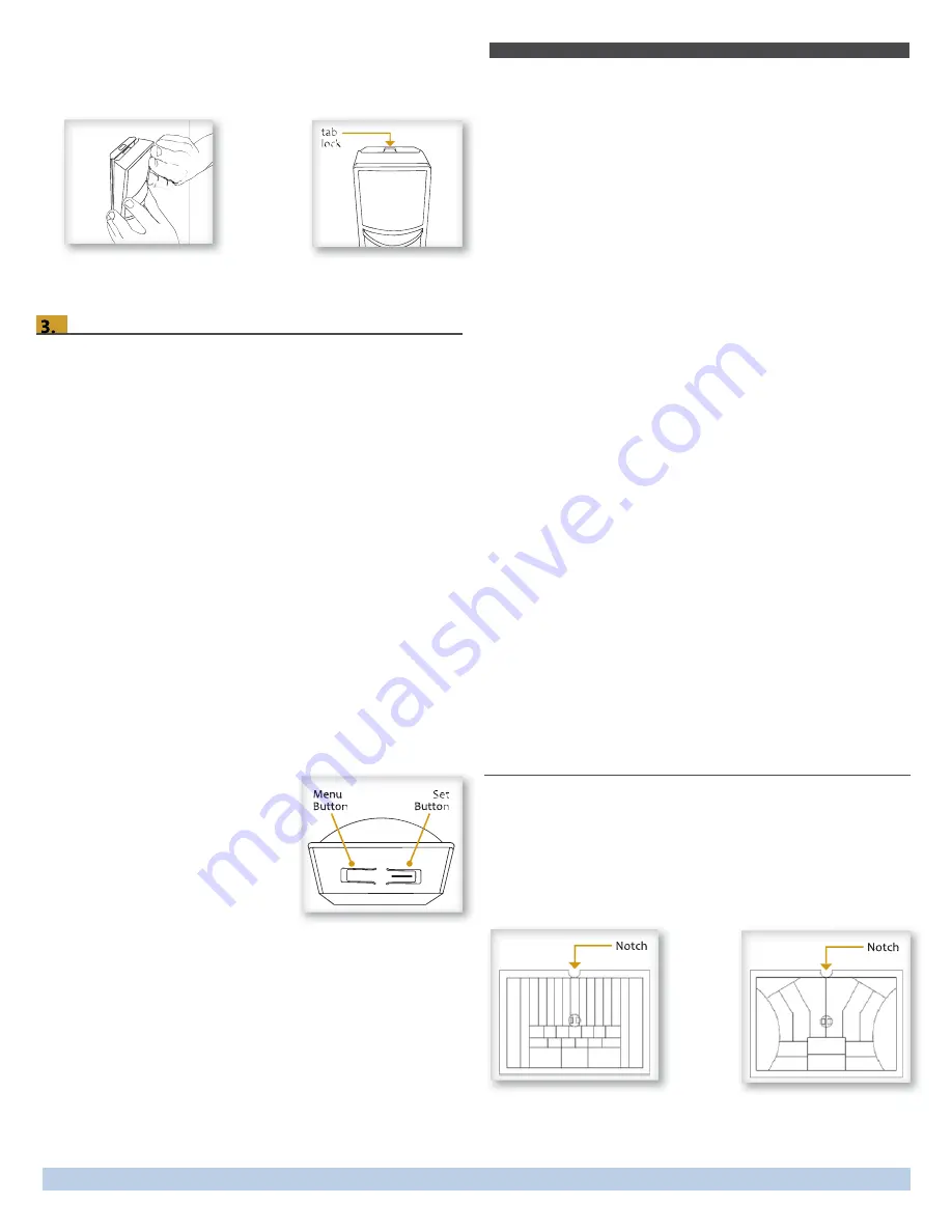
To Link or Unlink an Occupancy Sensor
1. Set the desired transceiver to the
desired Link/Unlink mode (refer
to that device’s installation guide).
2. Click the Menu button on the
bottom of the sensor once. This
sends a link/unlink radio
telegram.
NOTE: The button interface on the sensor is used for linking
and testing only. The occupancy timer settings are con
fi
g-
ured on the transceiver to which the sensor is linked.
Refer to the “Linking” section of the transceiver/controller
installation guides to complete the linking & setup process.
Testing the Sensor
Before starting a test, ensure the sensor’s energy storage is fully
charged by placing it under bright light (at least 500 lux) for 20
minutes, or insert a battery for 5 minutes while in a well-lit area.
NOTE: If the sensor does not have a suf
fi
cient charge, it cannot
enter into the test modes. No LED light or 1 red blink when the
d t d t t
ti
test button is pressed indicates insuf
fi
cient charge.
If a battery is used to charge the sensor for a light test, ensure it
is removed to get an accurate light measurement.
A test mode will stay active for 3 minutes. To exit a test and
resume normal operation, press and hold the Menu button for 5
seconds.
Walk Test
Use the walk test to con
fi
rm motion is within the sensor’s range.
1. Press and hold the Set button for 5 seconds.
••> Red LED will blink to con
fi
rm that a walk test is active.
2. Move in and out of the sensor‘s range to determine its cov-
erage area.
••> Sensor will blink when it detects motion.
3. Make small hand movements just inside the limit of the sen-
sor‘s range to see if the motion triggers a response.
NOTE: Ensure the sensor does not falsely trigger from user
activity outside the desired zone or other heat and motion
sources. If false triggering occurs, adjust the sensitivity switch
(next to the battery slot) from REG to LOW.
Light Test
Use the light test to measure real-time light levels and con
fi
rm
whether the occupancy sensor has suf
fi
cient light.
1. Create a realistic lighting condition (the test measures the
real-time light level).
2. Press and hold the Set button for 10 seconds.
••> Red & green LEDs will blink to con
fi
rm light test is active.
3. Watch the LED blink rate to determine the light strength.
••> The highest is 5 blinks which indicates very good light
(200 lux or more). 1 blink indicates minimum light (<25 lux).
NOTE: If there is no blink rate, consider relocating the sensor or
installing a battery to provide supplemental power.
Changing the Lens
The Occupancy Sensor package contains two lenses: a wide
angle lens and a long range lens. The wide angle lens is installed
by default and can be distinguished from the long range lens by
the pattern.
NOTE: Ensure smooth side of lens faces out.
Lens Patterns
Wide Angle Lens
Long Range Lens
g
g
de
g e e
Occupancy Sensor – Wall Mounted • Installation Guide
Page 3
© 2013 Hubbell Building Automation | www.hubbell-automation.com


