8 Post-Installation Check
No.
Description
Method
1
Do not place any materials on the chassis.
Observe
2
All vacant slots in a service subrack are filled in with filler panels.
Observe
3
All the cables are bound with proper tightness. The space between
the cable ties is even, and the remaining parts of the cable ties are
cut off neatly. All cable ties face the same direction, keeping the
overall appearance nice.
Observe
4
The cross sectional area of the power cable and ground cable
complies with the engineering design, and satisfy the requirements of
equipment running.
Observe
5
The power cable and ground cable adopt a whole segment of copper
core. The cable has no connection in the middle or scratch on the
skin.
Observe
6
The power cables and ground cables must be routed horizontally and
vertically without crossover. Proper margins must be reserved at the
turning.
Observe
7
The power cables and ground cables must be connected correctly
and reliably.
Observe
8
The identifiers on the power cable and ground cable must be correct,
legible, and neat.
Observe
9
The power cables, ground cables, and signal cables must be routed
separately.
Observe
10
Signal cables must be long enough, and must not be damaged or
broken, without joint in the cable.
Observe
11
The connectors of the signal cables must be neat and intact. The
connectors must be connected correctly and firmly. The tips must be
connected securely.
Observe
12
Labels at both ends of the signal cables must be marked correctly,
clearly and neatly.
Observe
13
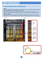
If the fibers must be routed outside the cabinet, protection measures
must be taken, such as using corrugated pipes or guide troughs.
Observe
14
Place the optical fiber pairs in order and bind them carefully with
optical binders. No sharp edge is allowed.
Observe
17

