background image


B.2 Requirements for Power Supply

This section describes the requirements for power supply conditions.

B.2.1 Requirements for AC Power Supply

The AC power supply consists of power mains, uninterruptable power supply (UPS), and self-
supplied electric generator. In addition to meeting the requirements of the server load, the AC
power supply must have a simple connection line, safe operation, flexible scheduling, and easy
maintenance.

The low-voltage power supply should have 3-phase, 5-wire mode or monophase 3-wire mode.
This AC power supply should be 110 V/127 V/220 V/380 V, and the frequency is 50 Hz.

The UPS should supply the same power and operate at the same phase as the power mains. The
switching time between the UPS and mains should be less than 10 ms; otherwise, the networking
devices will reboot or reset.

For power distribution capacity in the equipment room, both the working current and fault current
of the devices should be considered. Ensure that independent AC power supplies protect
independent devices. Configure the current-carrying capacity of the protection switch of the
equipment room for more than that of the devices.

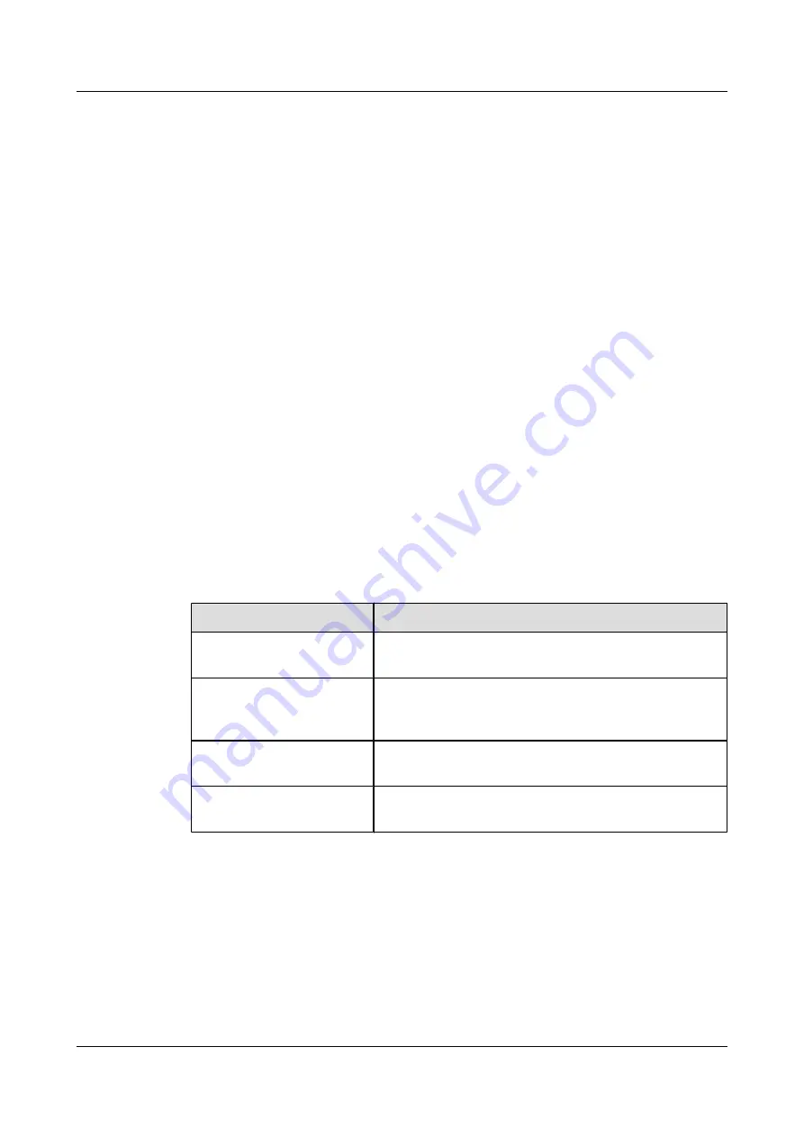
Table B-6

 shows the voltage range of the AC power supply for the devices.

Table B-6

 Voltage range of AC power supply

Item

Requirements

AC power capacity to support
the devices

-10% to +5% of the rated voltage

AC power capacity to support
the power modules and
important buildings

-15% to +10% of the rated voltage

Frequency of alternating
current

-15% to +10% of the rated voltage

Voltage wave shape sine
distortion

Within 5% of the rated voltage


The automated electric generator must have a standard interface that supports
telecommunication protocol, remote telecommunication, monitoring, and control.

AC power cables should meet the following specifications:

l

AC neutral should have a conductor with the same cross section as the phase line.

l

AC cables should have non-flammable insulation. The layout of AC cables should comply
with local regulations. Low-voltage power distribution rooms should comply with local
regulations.

HUAWEI NetEngine80E Router
Installation Guide

B Environmental Requirements for Device Operation

Issue 02 (2011-09-10)

Huawei Proprietary and Confidential

Copyright © Huawei Technologies Co., Ltd.

121

Summary of Contents for Quidway NE80E

Page 1: ...HUAWEI NetEngine80E Router V600R003C00 Installation Guide Issue 02 Date 2011 09 10 HUAWEI TECHNOLOGIES CO LTD ...

Page 2: ...be within the purchase scope or the usage scope Unless otherwise specified in the contract all statements information and recommendations in this document are provided AS IS without warranties guarantees or representations of any kind either express or implied The information in this document is subject to change without notice Every effort has been made in the preparation of this document to ensu...

Page 3: ...are described in the following table They are defined as follows Symbol Description Indicates a hazard with a high level of risk that if not avoided will result in death or serious injury Indicates a hazard with a medium or low level of risk which if not avoided could result in minor or moderate injury Indicates a potentially hazardous situation that if not avoided could cause device damage data l...

Page 4: ...fore the latest document version contains all updates made to previous versions Changes in Issue 02 2011 09 10 Second commercial release Updates in Issue 01 2011 05 30 Initial commercial release HUAWEI NetEngine80E Router Installation Guide About This Document Issue 02 2011 09 10 Huawei Proprietary and Confidential Copyright Huawei Technologies Co Ltd iii ...

Page 5: ...Package Container 11 2 3 2 Unpacking the Wooden Case 12 2 3 3 Unpacking the Carton 16 2 4 Checking the Boards 17 3 On site Cable Assembly and Installation 19 3 1 Cable Assembly Precautions 20 3 2 Assembling Power Cables 21 3 2 1 Assembling the OT Terminal and Power Cable 21 3 2 2 Assembling the JG Terminal and Power Cable 24 3 2 3 Assembling the Cord End Terminal and the Power Cable 27 3 3 Assembl...

Page 6: ...nterface Attributes 101 A 3 1 Interface Attributes of 10Base T 100Base TX 1000Base T RJ45 101 A 3 2 Interface Attributes of 100Base FX 101 A 3 3 Interface Attributes of 1000Base X SFP 102 A 3 4 Interface Attributes of 10GBase LAN WAN XFP 103 A 3 5 Interface Attributes of OC 3c STM 1c cPOS SFP 104 A 3 6 Interface Attributes of OC 3c STM 1c POS SFP 105 A 3 7 Interface Attributes of OC 12c STM 4c POS...

Page 7: ...ications for Laying Out Grounding Cables 127 D Engineering Labels for Cables 129 D 1 Introduction to Labels 130 D 1 1 Label Materials 130 D 1 2 Type and Structure 130 D 1 3 Label Printing 132 D 1 4 Writing Labels 134 D 1 5 Attaching Labels 135 D 1 6 Contents of Engineering Labels 137 D 1 7 Precautions for Using Engineering Labels 138 D 2 Engineering Labels for Optical Fibers 138 D 2 1 Labels for t...

Page 8: ... DC Power Distribution 5KW 152 E 1 2 Guide to the DC Power Distribution 8KW 155 E 1 3 Guide to the AC Power Distribution 158 HUAWEI NetEngine80E Router Installation Guide Contents Issue 02 2011 09 10 Huawei Proprietary and Confidential Copyright Huawei Technologies Co Ltd vii ...

Page 9: ... 1 Hardware Architecture the NE80E This section describes the appearance and structure of the NE80E 1 2 Cabinet Introduction This section describes the cabinet HUAWEI NetEngine80E Router Installation Guide 1 Device Introduction Issue 02 2011 09 10 Huawei Proprietary and Confidential Copyright Huawei Technologies Co Ltd 1 ...

Page 10: ...69 mm x 1600 mm width x depth x height Figure 1 1 shows the outline of the NE80E Figure 1 1 NE80E outline mm 17 4 in mm 62 99 in Figure 1 2 shows the main components of the NE80E HUAWEI NetEngine80E Router Installation Guide 1 Device Introduction Issue 02 2011 09 10 Huawei Proprietary and Confidential Copyright Huawei Technologies Co Ltd 2 ...

Page 11: ...hnical Commission IEC 19 inch standard cabinet For the latter one the depth should not be less than 800 mm 31 50 in and its column should be at a distance of 100 mm 3 94 in away from the front door The N68E 22 interior is 46 U 2044 7 mm or 80 50 in high and its dimensions are 600 mm x 800 mm x 2200 mm 23 62 in x 31 50 in x 86 61 in The outline of the N68E 22 cabinet is shown in Figure 1 3 HUAWEI N...

Page 12: ...Figure 1 3 N68E 22 cabinet outline HUAWEI NetEngine80E Router Installation Guide 1 Device Introduction Issue 02 2011 09 10 Huawei Proprietary and Confidential Copyright Huawei Technologies Co Ltd 4 ...

Page 13: ...he skills that the installation engineers must possess and the requirements that the installation engineers must meet 2 2 Checking the Installation Environment This topic describes the requirements for checking the hardware installation environment 2 3 Unpacking and Checking the Products This topic describes the procedure and precaution for unpacking and checking the products after the engineering...

Page 14: ...ided by Huawei Technologies Co Ltd and is delivered to the site along with the device Installation engineers can install operate and maintain the device with reference to the disk l Other documents related to the engineering include the Contract Agreement and the Packing List They are provided by Huawei Technologies Co Ltd to the customer when the device is delivered 2 1 2 Preparing Tools and Mete...

Page 15: ...n engineers to perform this activity the customer needs to pay attention to the following points l The installation engineer must have been trained and certified by Huawei Technologies Co Ltd and must understand the methods of installing and commissioning the system The installation engineer must obtain a qualification certificate before installing and commissioning the device l The technical engi...

Page 16: ... can connect the floor material or the movable floor to the grounding unit by using the current limiting resistor and the connection line The resistance of the current limiting resistor is 1 megohm l The door and windows must be installed with dust proof plastic sealing tapes It is recommended to install the windows with double layer glass and seal them strictly l The wall must be processed by usi...

Page 17: ...er supply faults occur 2 2 4 Checking the Grounding Good grounding is the basis of stable running of the device It is also the prerequisite for protecting the device from lightning strike and interference Be sure to check the grounding condition of the installation site carefully and implement good grounding based on the actual situations Checking the Grounding of the Equipment Room l The equipmen...

Page 18: ... protection grounding bar that is provided and used by the customer Checking the Grounding of the Signal Cable l Use the shielded cable or the cable with metal jacket as the signal cable that is led in to or led out from the site The same is recommended strongly The free line in the cable must be grounded inside the equipment room l The shielded layer metal jacket or metal tube of the cable that i...

Page 19: ...he Packing List or the products are delivered to the wrong destination Perform step 3 Step 3 The engineering supervisor must send the Cargo Inspection Feedback Form that is confirmed and signed by the customer to the order management engineer in the local Huawei representative office within three days At the same time stop unpacking the products Step 4 Check whether the exterior of the package con...

Page 20: ...rt force on the parts that are relatively weak such as the cable support or the cable fixing beam Otherwise the cabinet may get damaged or accidents may occur Remove the backing blocks from the rack only after the cabinet is carried to the installation site The same is to avoid damaging signal cables and boards when carrying the cabinet l The wooden case must be positioned correctly Do not place t...

Page 21: ...tongues are sharp and may injure your hand Step 4 After straightening all the tongues on the cover remove the cover as shown in Figure 2 2 HUAWEI NetEngine80E Router Installation Guide 2 Preparing for the Installation Issue 02 2011 09 10 Huawei Proprietary and Confidential Copyright Huawei Technologies Co Ltd 13 ...

Page 22: ...es that join the side wooden panels and remove the wooden panels as shown in Figure 2 3 HUAWEI NetEngine80E Router Installation Guide 2 Preparing for the Installation Issue 02 2011 09 10 Huawei Proprietary and Confidential Copyright Huawei Technologies Co Ltd 14 ...

Page 23: ...rsons are required to stand the cabinet When standing the cabinet prevent the cabinet from tipping over as this may cause injury to the personnel who are handling it HUAWEI NetEngine80E Router Installation Guide 2 Preparing for the Installation Issue 02 2011 09 10 Huawei Proprietary and Confidential Copyright Huawei Technologies Co Ltd 15 ...

Page 24: ...t the packing straps Step 3 Use a paper knife to cut the tapes along the seams of the carton cover Do not insert the paper knife to extra depths otherwise the contents inside the carton may get damaged Step 4 Open the carton and take out the foam plates Step 5 Check the label of the box that contains the board and see whether the board quantity is consistent with the quantity indicated on the cart...

Page 25: ... from the antistatic package Check whether the board name is consistent with the identifier on the package box and whether any device is damaged or any component is missing Check pins on the backplane of the chassis The pins should be kept straight orderly and clean For the pins bent in the board slots on the backplane repair them The boards are sensitive to Electrostatic Discharge ESD When handli...

Page 26: ... to replace chips Do not tough chips circuits or pins with your bare hands l Keep the board and other ESD sensitive parts to be installed in antistatic bags Place the removed boards and components on an antistatic pad or other antistatic materials Do not use non antistatic materials such as white foams common plastic bags or paper bags to pack boards or let them touch boards l Wear an antistatic w...

Page 27: ...45 connectors and Category 5 cable to make Ethernet cables 3 4 Installing Cable Accessories This section describes how to install the cable accessories such as power adapters network adapters coaxial connectors SCSI connectors and XLR connectors 3 5 Attaching Engineering Labels Engineering labels are used for equipment installation and maintenance The labels help to ensure smooth installations and...

Page 28: ... here during assembly l Hold terminals of cables instead of pulling the cables when installing or removing cable components l Take the following precautions when cutting or stripping cables Make cables slightly longer than necessary Coil cables longer than 2 m 6 56 ft after cutting Bind and fasten the coils using bundling ropes The inner diameters of the coils should be larger than 20 times the ou...

Page 29: ...a power cable Context Figure 3 1 shows the components of an OT terminal and a power cable Figure 3 1 Components of an OT terminal and a power cable A Heat shrinkable tubing B Bare crimping terminal C Insulation D Conductor Procedure Step 1 Based on the cross sectional area of the cable conductor strip a part of the insulation This exposes length L1 of the conductor as shown in Figure 3 2 The recom...

Page 30: ...onductor mm2 in 2 Value of L1 mm in 1 0 002 7 0 28 10 0 015 11 0 43 1 5 0 002 7 0 28 16 0 025 13 0 51 2 5 0 004 7 0 28 25 0 039 14 0 55 4 0 006 8 0 31 35 0 054 16 0 63 6 0 009 9 0 35 50 0 077 16 0 63 NOTE If you are proficient in assembling OT terminals and power cables you can obtain the value of L1 by comparing the part to be crimped with the power cable Step 2 Put the heat shrinkable A tubing o...

Page 31: ...ep 4 Crimp the joint parts of the bare crimping terminal and the conductor as shown in Figure 3 4 NOTE The shapes of crimped parts may vary with the crimping dies Figure 3 4 Crimping the joint parts of the bare crimping terminal and the conductor Step 5 Push the heat shrink tubing A towards the connector until the tube covers the crimped part and then heat the tube by using a heat gun as shown in ...

Page 32: ...er cable Context Figure 3 6 shows the components of a JG terminal and a power cable Figure 3 6 Components of a JG terminal and a power cable A JG terminal B Heat shrinkable tube C Insulation layer of a power cable D Conductor of a power cable HUAWEI NetEngine80E Router Installation Guide 3 On site Cable Assembly and Installation Issue 02 2011 09 10 Huawei Proprietary and Confidential Copyright Hua...

Page 33: ... the value of L as required Figure 3 7 Stripping a power cable JG terminal Table 3 2 Mapping between the cross sectional area of the conductor and the value of L Cross Sectional Area of Conductor mm2 in 2 Value of L mm in 16 0 025 13 0 51 25 0 039 14 0 55 35 0 054 16 0 63 50 0 077 16 0 63 Step 2 Put the heat shrink tubing onto the bare crimping terminal as shown in Figure 3 8 HUAWEI NetEngine80E R...

Page 34: ... conductor as shown in Figure 3 9 Figure 3 9 Crimping the joint parts of the bare crimping terminal and the conductor JG terminal Step 5 Push the heat shrink tubing towards the connector until the tube covers the crimped part and then heat the tube by using a heat gun as shown in Figure 3 10 Figure 3 10 Heating the heat shrink tubing JG terminal HUAWEI NetEngine80E Router Installation Guide 3 On s...

Page 35: ...r of a power cable C Conductor of a power cable Procedure Step 1 Based on the cross sectional area of the cable conductor strip a part of the insulation The L1 long conductor is exposed as shown in Figure 3 12 The recommended values of L1 are listed in Table 3 3 CAUTION When you strip a power cable do not damage the conductor of the cable HUAWEI NetEngine80E Router Installation Guide 3 On site Cab...

Page 36: ...39 18 0 71 4 0 006 12 0 47 35 0 054 19 0 75 6 0 009 14 0 55 50 0 077 26 1 02 Step 2 Putting the cord end terminal onto the conductor and ensure that the conductor is aligned with the edge of the cord end terminal as shown in Figure 3 13 CAUTION After the conductor is fed into the cord end terminal the protruding part of the conductor must not be longer than 1 mm 0 04 in HUAWEI NetEngine80E Router ...

Page 37: ...ular crimped terminal is listed in Table 3 4 Table 3 4 Maximum width of a tubular crimped terminal Cross Sectional Area of Tubular Terminal mm2 in 2 Maximum Width of Crimped Terminal W1 mm in 0 25 0 0004 1 0 04 0 5 0 0008 1 0 04 1 0 0 0015 1 5 0 06 1 5 0 0023 1 5 0 06 2 5 0 0039 2 4 0 09 4 0 006 3 1 0 12 6 0 009 4 0 16 HUAWEI NetEngine80E Router Installation Guide 3 On site Cable Assembly and Inst...

Page 38: ...mble a shielded RJ45 connector and an Ethernet cable or specifically a straight through cable Context Figure 3 15 shows the components of an RJ45 connector and a shielded Ethernet cable Figure 3 15 Shielded RJ45 connector and cable A Jacket of connector B Metal shell of connector C Wire holder of connector D Plug of connector E Jacket of Ethernet cable F Shielding layer of Ethernet cable G Twisted...

Page 39: ...emove a section of the jacket do not damage the shield layer of the twisted pair cable l When you remove the shield layer do not damage the insulation of the twisted pair cable Figure 3 17 Removing the jacket of a twisted pair cable unit mm in Step 3 Fit the metal shell onto the twisted pair cable The shield layer is covered by the metal shell as shown in Figure 3 18 HUAWEI NetEngine80E Router Ins...

Page 40: ...pair cable is about 20 mm 0 79 in long as shown in Figure 3 19 Figure 3 19 Removing the shield layer of a twisted pair cable unit mm in Step 5 Based on the colors lead the four pairs of twisted pair wires through the wire holder as shown in Figure 3 20 and Figure 3 21 Figure 3 20 Leading wires through the wire holder HUAWEI NetEngine80E Router Installation Guide 3 On site Cable Assembly and Instal...

Page 41: ... and the pins are shown in Figure 3 23 and listed in Table 3 5 Figure 3 22 Four pairs of cables on a wire holder Figure 3 23 Connections between wires and pins Brown White Brown Green White Blue Blue White Green Orange White Orange Pin 8 Pin 1 HUAWEI NetEngine80E Router Installation Guide 3 On site Cable Assembly and Installation Issue 02 2011 09 10 Huawei Proprietary and Confidential Copyright Hu...

Page 42: ...re holder as shown in Figure 3 24 Figure 3 24 Cutting off surplus cables Step 8 Put the connector body onto the wire holder and turn the metal shell by 90 as shown in Figure 3 25 NOTE Ensure that the wire holder is in good contact with the connector body HUAWEI NetEngine80E Router Installation Guide 3 On site Cable Assembly and Installation Issue 02 2011 09 10 Huawei Proprietary and Confidential C...

Page 43: ...e 3 26 Crimping the connector Step 10 Push the jacket towards the metal shell until the metal shell is covered This completes the assembly of one end of the cable as shown in Figure 3 27 Figure 3 27 Pushing the metal shell HUAWEI NetEngine80E Router Installation Guide 3 On site Cable Assembly and Installation Issue 02 2011 09 10 Huawei Proprietary and Confidential Copyright Huawei Technologies Co ...

Page 44: ... Figure 3 28 Components of an unshielded RJ45 connector and cable A B C A Plug of connector B Jacket C Twisted pair wires Procedure Step 1 Remove a 30 mm 1 18 in long section of the jacket as shown in Figure 3 29 CAUTION When you remove the shield layer do not damage the insulation of the twisted pair cable Figure 3 29 Removing the jacket of a twisted pair cable unit mm in HUAWEI NetEngine80E Rout...

Page 45: ...ctions between wires and pins Matching Pins of Wires Core Wire Color 1 Brown 2 White Brown 3 Green 4 White Blue 5 Blue 6 White Green 7 Orange 8 White Orange Step 3 Feed the cable into the plug and crimp the connector as shown in Figure 3 31 NOTE Ensure that the cable is in good contact with the plug Figure 3 31 Crimping the connector HUAWEI NetEngine80E Router Installation Guide 3 On site Cable As...

Page 46: ... with the RJ45 socket The plastic separators must remain intact and be aligned l The contact strip blade must extend beyond the ends of the wires The ends of the wires must be in contact with the edge of the RJ45 The distance between them must be less than 0 5 mm 0 02 in Procedure Step 1 Hold the crimped connector with the front side facing you and check whether the contact strips are of the same ...

Page 47: ...annot be removed replace it with a new RJ45 connector Figure 3 35 shows an unqualified piece Figure 3 35 Dirt on a contract strip Step 4 Check whether the contact strips and the plastic separators are well aligned and intact If a separator is skew and cannot be fixed replace it with a new RJ45 connector Figure 3 36 shows an unqualified piece HUAWEI NetEngine80E Router Installation Guide 3 On site ...

Page 48: ... Assembled Cables This topic describes how to test an assembled Ethernet cable ensuring that the connectors and wires at both ends are correctly connected This topic illustrates how to test a straight through cable Context Huawei provides two types of Ethernet cables straight through cables and crossover cables l Straight through cables are connected in a one to one manner They are used to connect...

Page 49: ...he connections of core wires in a crossover cable Table 3 8 Connections of core wires in a straight crossover cable RJ45 Connector 1 RJ45 Connector 2 Core Wire Color Twisted or Not 6 2 Orange Twisted 3 1 Orange White 2 6 Green Twisted 1 3 Green White 4 4 Blue Twisted 5 5 Blue White 8 8 Brown Twisted 7 7 Brown White Figure 3 38 shows the pins of an RJ45 connector Figure 3 38 Pins of an RJ45 connect...

Page 50: ...check whether the indicators turn on simultaneously as shown in Figure 3 39 Figure 3 39 Testing the conduction and connections of wires Step 3 Gently shake the connector and repeat Step 2 to check whether the metal contact strips are in good contact with the core wires and Ethernet ports as shown in Figure 3 40 Figure 3 40 Checking the reliability HUAWEI NetEngine80E Router Installation Guide 3 On...

Page 51: ...a multimeter to perform a simple test as shown in Figure 3 41 Figure 3 41 Testing the connection of an Ethernet cable End 3 4 Installing Cable Accessories This section describes how to install the cable accessories such as power adapters network adapters coaxial connectors SCSI connectors and XLR connectors 3 4 1 Precautions for Installing Cable Accessories Tools NOTE The illustrations in this doc...

Page 52: ...ors ensure that the connectors are properly connected with their adapters Use flathead or Phillips head screwdrivers and do not use too much force To avoid damaging screws or adapters do not tighten the screws forcibly l When removing densely aligned cables or fiber connectors use dedicated pliers such as cable pulling pliers and fiber pulling pliers l Do not twist bend stretch or extrude fibers d...

Page 53: ...T terminals on a post Procedure l Install an OT terminal 1 Align the hole of the OT terminal conductor upward with a connecting hole as shown in Figure 3 42 Figure 3 42 Aligning the OT terminal with a connecting hole NOTE When you install an OT terminal the crimping sleeve is installed as shown in Figure 3 43 where A is correct and B is wrong Figure 3 43 Installing an OT terminal showing the orien...

Page 54: ... two OT terminals on a post Before you install two OT terminals on a post ensure that the two terminals can be installed on the post and that the electrical connecting pieces have a large contact area Two OT terminals can be installed using any of these methods Bend the upper OT terminal at a 45 or 90 degree angle as shown in Figure 3 46 Cross the two terminals as shown in Figure 3 47 HUAWEI NetEn...

Page 55: ...minal at a 45 or 90 degree angle Figure 3 47 Crossing two terminals Figure 3 48 Installing two terminals back to back HUAWEI NetEngine80E Router Installation Guide 3 On site Cable Assembly and Installation Issue 02 2011 09 10 Huawei Proprietary and Confidential Copyright Huawei Technologies Co Ltd 47 ...

Page 56: ...t on a terminal jack as shown in Figure 3 49 To ensure bump contact and dense connection place the plain side of the terminal outwards Figure 3 49 Placing a terminal on a terminal jack vertically Step 2 Insert the terminal into the jack vertically and fasten the terminal by turning the matching screw in the clockwise direction as shown in Figure 3 50 Figure 3 50 Feeding the terminal into the jack ...

Page 57: ...f the terminal Step 3 Move the cable slightly and ensure that it is securely connected as shown in Figure 3 52 Figure 3 52 Installed cord end terminal Step 4 Before you remove a cord end terminal loosen the screw in the counterclockwise direction End HUAWEI NetEngine80E Router Installation Guide 3 On site Cable Assembly and Installation Issue 02 2011 09 10 Huawei Proprietary and Confidential Copyr...

Page 58: ...e connector as shown in Figure 3 53 Figure 3 53 Holding the male and female connectors Step 2 Insert the male connector into the female connector as shown in Figure 3 54 Figure 3 54 Feeding the male connector into the female connector Step 3 Pull the connector slightly and ensure that it is securely connected HUAWEI NetEngine80E Router Installation Guide 3 On site Cable Assembly and Installation I...

Page 59: ... Unshielded Ethernet Connector This section describes how to install an unshielded Ethernet connector Procedure Step 1 Hold the male and female connectors with the male connector facing the female connector as shown in Figure 3 57 HUAWEI NetEngine80E Router Installation Guide 3 On site Cable Assembly and Installation Issue 02 2011 09 10 Huawei Proprietary and Confidential Copyright Huawei Technolo...

Page 60: ...sp click indicates that the connector is locked by the locking key Pull the connector slightly and ensure that it is securely connected Figure 3 59 shows an installed Ethernet connector Figure 3 59 Installed Ethernet connector HUAWEI NetEngine80E Router Installation Guide 3 On site Cable Assembly and Installation Issue 02 2011 09 10 Huawei Proprietary and Confidential Copyright Huawei Technologies...

Page 61: ...tool if the connectors are densely installed Instructions on How to Use an Optical Module NOTE Use only the modules supplied by HUAWEI Precautions for the loosened optical module l When installing an optical module force it into position If a crack sound is heard or a slight tremor is felt it indicates that the latch boss is secured When the latch boss is not secured the connecting finger is unsta...

Page 62: ... the receptacle This protects the receptacle against the contamination on the end surface of the optical connector NOTE Use at least three cleaning tissues Wipe the end of an optical connector horizontally in one direction and then move the connector end to the unused part of the cleaning tissue to continue Generally one cleaning tissue can be used once for cleaning an optical connector l To preve...

Page 63: ...sed to clean an optical connector NOTE During the cleaning process insert the cotton swab and turn it slowly in the receptacle Do not use too much strength because the receptacle may be damaged l If optical signals are lost during the operation of a device use the preceding method to clean the receptacle or the optical connector In this manner the possibility of contamination can be excluded HUAWE...

Page 64: ...oid damages to the receptacle l Mixed use of multi mode and single mode optical fibers is prohibited Otherwise faults such as signal loss may occur Cleaning Fiber Connectors This section describes how to clean fiber connectors Procedure Step 1 Clean the pins of a fiber connector by using lint free cotton and alcohol Step 2 Clean the pins again by using dust free cotton If necessary clean the pins ...

Page 65: ... Step 3 Feed the male connector into the female connector as shown in Figure 3 62 Figure 3 62 Feeding the male connector into the female connector Step 4 Fasten the locking nut in the clockwise direction and ensure that the connector is securely installed as shown in Figure 3 63 HUAWEI NetEngine80E Router Installation Guide 3 On site Cable Assembly and Installation Issue 02 2011 09 10 Huawei Propr...

Page 66: ...r This section describes how to install an LC fiber connector Procedure Step 1 Remove the dustproof cap of the LC fiber connector and store it for future use Step 2 Align the core pin of the male connector with that of the female connector as shown in Figure 3 65 HUAWEI NetEngine80E Router Installation Guide 3 On site Cable Assembly and Installation Issue 02 2011 09 10 Huawei Proprietary and Confi...

Page 67: ...nector Step 4 A clicking sound indicates that the male connector is locked as shown in Figure 3 67 Figure 3 67 Installed LC connector Step 5 To disassemble an LC fiber connector press the locking nut as shown in Figure 3 68 HUAWEI NetEngine80E Router Installation Guide 3 On site Cable Assembly and Installation Issue 02 2011 09 10 Huawei Proprietary and Confidential Copyright Huawei Technologies Co...

Page 68: ...onnector with that of the female connector as shown in Figure 3 69 Figure 3 69 Aligning the male connector with the female connector Step 3 Feed the male connector into the female connector until you hear a clicking sound The male and female connectors are securely installed as shown in Figure 3 70 HUAWEI NetEngine80E Router Installation Guide 3 On site Cable Assembly and Installation Issue 02 201...

Page 69: ...or This section describes how to install an MTRJ fiber connector Procedure Step 1 Remove the dustproof cap of the MTRJ fiber connector and store it for future use Step 2 Align the core pin of the male connector with that of the female connector as shown in Figure 3 72 HUAWEI NetEngine80E Router Installation Guide 3 On site Cable Assembly and Installation Issue 02 2011 09 10 Huawei Proprietary and ...

Page 70: ...ng the male connector into the female connector Step 4 A clicking sound indicates that the male connector is locked as shown in Figure 3 74 Figure 3 74 Installed MTRJ fiber connector HUAWEI NetEngine80E Router Installation Guide 3 On site Cable Assembly and Installation Issue 02 2011 09 10 Huawei Proprietary and Confidential Copyright Huawei Technologies Co Ltd 62 ...

Page 71: ...e Step 1 Remove the dustproof cap of the MPO fiber connector and store it for future use Step 2 Align the core pin of the male connector with that of the female connector as shown in Figure 3 76 Figure 3 76 Aligning the male connector with the female connector HUAWEI NetEngine80E Router Installation Guide 3 On site Cable Assembly and Installation Issue 02 2011 09 10 Huawei Proprietary and Confiden...

Page 72: ... shell labeled PULL and remove the male connector as shown in Figure 3 78 Figure 3 78 Disassembling an MPO fiber connector End 3 5 Attaching Engineering Labels Engineering labels are used for equipment installation and maintenance The labels help to ensure smooth installations and facilitate future maintenance HUAWEI NetEngine80E Router Installation Guide 3 On site Cable Assembly and Installation ...

Page 73: ...GND cables must not have row or column numbers MN BC 48 V2 MN BC GND MN BC PGND NOTE The GND and PGND are copper bars All the wiring terminals on a copper bar are electrically connected Thus only the row and column information of the PDFs is required For example a cable labeled with A01 GND is connected to the GND bar in row A column 01 The label for a cable connected to a PGND bar is marked in th...

Page 74: ...he plate Consistency however must be maintained in actual situations Step 3 Bind the cable tie 20 mm 0 79 in away from the plug as shown in Figure 3 81 NOTE By default the label is attached 20 mm 0 79 in away from the connector If required you can change the position to facilitate smooth installation Consistency and neatness however must be maintained Figure 3 81 Binding the cable tie A05 PGND Ste...

Page 75: ...ing pliers as shown in Figure 3 83 and Figure 3 84 Figure 3 83 Cutting off the surplus part of the cable tie Figure 3 84 Installed label HUAWEI NetEngine80E Router Installation Guide 3 On site Cable Assembly and Installation Issue 02 2011 09 10 Huawei Proprietary and Confidential Copyright Huawei Technologies Co Ltd 67 ...

Page 76: ...attach the long end of the label to the cable as shown in Figure 3 85 Figure 3 85 Attaching an engineering label Step 2 Attach the label 20 mm 0 79 in away from the connector and turn over the long end Ensure that the long end is aligned with the label NOTE By default the label is attached 20 mm 0 79 in away from the connector If required you can change the position to facilitate smooth installati...

Page 77: ...nd align the upper edge with the lower edge as shown in Figure 3 87 and Figure 3 88 Figure 3 87 Folding the lower edge upwards HUAWEI NetEngine80E Router Installation Guide 3 On site Cable Assembly and Installation Issue 02 2011 09 10 Huawei Proprietary and Confidential Copyright Huawei Technologies Co Ltd 69 ...

Page 78: ...in the counterclockwise direction as shown in Figure 3 89 Figure 3 89 Loosening two fastening screws Step 2 Hold the handles of the COAX crimping tools to open the self locking mechanism The jaw of the COAX crimping tools opens automatically as shown in Figure 3 90 HUAWEI NetEngine80E Router Installation Guide 3 On site Cable Assembly and Installation Issue 02 2011 09 10 Huawei Proprietary and Con...

Page 79: ... mould from the COAX crimping tools Step 4 Place the mould to be installed into the jaw of the COAX crimping tools and align the screw holes as shown in Figure 3 92 HUAWEI NetEngine80E Router Installation Guide 3 On site Cable Assembly and Installation Issue 02 2011 09 10 Huawei Proprietary and Confidential Copyright Huawei Technologies Co Ltd 71 ...

Page 80: ...e mould and the jaw completely Align the screw holes as shown in Figure 3 93 Figure 3 93 Aligning the screw holes Step 6 Hold the handles of the COAX crimping tools with one hand Tighten the two fastening screws in the clockwise direction Figure 3 94 shows the mould installed in the COAX crimping tools HUAWEI NetEngine80E Router Installation Guide 3 On site Cable Assembly and Installation Issue 02...

Page 81: ... shows the mold installed in the crimping pliers Figure 3 95 An installed mold End HUAWEI NetEngine80E Router Installation Guide 3 On site Cable Assembly and Installation Issue 02 2011 09 10 Huawei Proprietary and Confidential Copyright Huawei Technologies Co Ltd 73 ...

Page 82: ...E80E in a Cabinet 4 2 Laying out Ground Cable and Power Cables 4 3 Installing Boards 4 4 Laying Out Network Cables 4 5 Laying Out Optical Fibers HUAWEI NetEngine80E Router Installation Guide 4 Installing NE80E Issue 02 2011 09 10 Huawei Proprietary and Confidential Copyright Huawei Technologies Co Ltd 74 ...

Page 83: ...er during the transportation after unpacking l Wear gloves during unpacking cases to protect your hands 1 Adjusting the height of the slide rail 1U 44 5mm The height of three holes on the mounting rails is 1U 2 Positioning captive nuts using rack mounting ear HUAWEI NetEngine80E Router Installation Guide 4 Installing NE80E Issue 02 2011 09 10 Huawei Proprietary and Confidential Copyright Huawei Te...

Page 84: ...captive nuts 4 Installing a rack mounting ear NOTE The NE80E need to install two rack mounting ears HUAWEI NetEngine80E Router Installation Guide 4 Installing NE80E Issue 02 2011 09 10 Huawei Proprietary and Confidential Copyright Huawei Technologies Co Ltd 76 ...

Page 85: ...et NOTE The chassis is heavy so the preceding operations require four people HUAWEI NetEngine80E Router Installation Guide 4 Installing NE80E Issue 02 2011 09 10 Huawei Proprietary and Confidential Copyright Huawei Technologies Co Ltd 77 ...

Page 86: ...und cables do not connect them to the power supply device Ground cable of the cabinet Ground cable of the NE80E 1 Connecting the N68E cabinet to the ground HUAWEI NetEngine80E Router Installation Guide 4 Installing NE80E Issue 02 2011 09 10 Huawei Proprietary and Confidential Copyright Huawei Technologies Co Ltd 78 ...

Page 87: ...s to the grounding bar Laying out DC Power Cables NEG cable RTN cable Connecting one end of the power cables to the PDF HUAWEI NetEngine80E Router Installation Guide 4 Installing NE80E Issue 02 2011 09 10 Huawei Proprietary and Confidential Copyright Huawei Technologies Co Ltd 79 ...

Page 88: ...g out AC Power Cables AC power cable C19 cable HUAWEI NetEngine80E Router Installation Guide 4 Installing NE80E Issue 02 2011 09 10 Huawei Proprietary and Confidential Copyright Huawei Technologies Co Ltd 80 ...

Page 89: ...g the power cables Connecting one end of the power cables to the PDF 4 After installing the cables install the baffle to the AC power distribution box HUAWEI NetEngine80E Router Installation Guide 4 Installing NE80E Issue 02 2011 09 10 Huawei Proprietary and Confidential Copyright Huawei Technologies Co Ltd 81 ...

Page 90: ... on the chassis to decide whether the board is installed in a proper slot On the NE80Ean interface is numbered in the format of slot number card number port number l The slots of LPUs are numbered from 1 to 16 l The card is numbered from 0 l The interface is numbered from 0 Installing Boards Board cage HUAWEI NetEngine80E Router Installation Guide 4 Installing NE80E Issue 02 2011 09 10 Huawei Prop...

Page 91: ... U L P U L P U L P U L P U L P U S F U S F U S F U S F U L P U L P U L P U 1 Removing the dummy panels on the slot and motherboard 2 Installing the SRU SFU and LPU HUAWEI NetEngine80E Router Installation Guide 4 Installing NE80E Issue 02 2011 09 10 Huawei Proprietary and Confidential Copyright Huawei Technologies Co Ltd 83 ...

Page 92: ...lling an FPIC 4 Installing an High density FPIC HUAWEI NetEngine80E Router Installation Guide 4 Installing NE80E Issue 02 2011 09 10 Huawei Proprietary and Confidential Copyright Huawei Technologies Co Ltd 84 ...

Page 93: ...network cables bound to a bundle should not be more than 20 Bind the network cables in the cabinet to rectangles Fix the network cables on the fiber bundlers Bind the network cables with a cable tie every 200 mm The wire clip must be tidy and in the same direction after the network cables are bound HUAWEI NetEngine80E Router Installation Guide 4 Installing NE80E Issue 02 2011 09 10 Huawei Propriet...

Page 94: ...k is required connect the cables based on the site survey HUAWEI NetEngine80E Router Installation Guide 4 Installing NE80E Issue 02 2011 09 10 Huawei Proprietary and Confidential Copyright Huawei Technologies Co Ltd 86 ...

Page 95: ... than 60 Lead the optical fiber through a corrugated pipe The mouth of the corrugated pipe must be wrapped with the adhesive tape The bending radius of the optical fiber should be more than 20 times the cable diameter In general the bending radius of the optical fiber is more than or equal to 40 mm Affix the labels to the optical fibers at 20 mm away from the connectors at both ends HUAWEI NetEngi...

Page 96: ...HUAWEI NetEngine80E Router Installation Guide 4 Installing NE80E Issue 02 2011 09 10 Huawei Proprietary and Confidential Copyright Huawei Technologies Co Ltd 88 ...

Page 97: ...you complete the hardware installation you need to check the installation of the devices and cables 5 2 Powering on a Device 5 3 Checking After Powering on a Device 5 4 Powering off a Device HUAWEI NetEngine80E Router Installation Guide 5 Powering on Devices Issue 02 2011 09 10 Huawei Proprietary and Confidential Copyright Huawei Technologies Co Ltd 89 ...

Page 98: ...ure that the switches of all power distribution units PDUs and power distribution frames PDFs are in the OFF state Table 5 1 lists the items that need to be checked for the installed device Table 5 1 Checklist for the installed device No Check Item and Description Method 1 The cabinet is placed as required in the design drawing Check this according to the engineering design document 2 The expansio...

Page 99: ...h other Rows of cabinets are aligned along the main aisle with a deviation of up to 5 mm 5 The accessories on the front and back doors of the cabinet are present A connecting plate is installed if two cabinets are attached to each other 6 The front door of the cabinet can be opened and closed smoothly Check this by unlocking the door according to the following figure Check this by locking the door...

Page 100: ...traps cable ends or other foreign objects inside the cabinet 10 The electrostatic discharge ESD preventive wrist strap is inserted into the ESD preventive hole on the cabinet Check this according to the following figure 11 Blank filler panels are installed in all empty slots 5 1 2 Cable Installation Checklist This section provides a checklist for checking the installed cables Power Cables and Grou...

Page 101: ...re 5 The extra ends of the power cables and grounding cables are cut off instead of being coiled 6 The grounding cable for the cabinet door is connected reliably and firmly 7 Each power cable or grounding cable must be labeled according to the standards The labels are stuck on a fixed position on the cables and they face the same direction including the label on the power distribution switch It is...

Page 102: ...passed the continuity test before they are laid 2 The signal cables are not laid over the heat dissipation mesh of the cabinet 3 Adequate space is provided for the cables at the turning points The cables cannot be compressed at the turning points Check this according to the following figure 4 The cables are straight and smooth The cables inside the cabinet are not crossed and the cables outside th...

Page 103: ...e 8 series router is working properly the green indicators PWR IN and PWR OUT are always on and the red indicator ALM is always off l Whether the indicators of each fan module are normal If a fan module on the X3 X8 X16 series router is working properly the indicator STATUS blinks green If a fan module on the 8 series router is working properly the green indicator RUN blinks and the red indicator ...

Page 104: ... Power Consumption and Weight A 3 List of LPU Interface Attributes This chapter presents the list of LPU Interface Attributes HUAWEI NetEngine80E Router Installation Guide A Parameters Issue 02 2011 09 10 Huawei Proprietary and Confidential Copyright Huawei Technologies Co Ltd 96 ...

Page 105: ...100 kg 220 5 lb NE80E Empty chassis 120 kg 264 6 lb Full chassis 294 kg 648 27 lb A 2 Power Consumption and Weight Table A 3 shows the nominal weight and power consumption of the boards Table A 3 Power consumption and weight of the boards Board Name Power Consumpti on Heat Dissipatio n Weight Main Processing Unit CR52 MPUB2 78 W 253 BTU hour 3 8 kg 8 38 lb Switch Fabric Unit CR52 SFUG 95 W 308 BTU...

Page 106: ... 50 kg 1 10 lb 2 port OC 12c STM 4c ATM SFP FPIC 24 W 78 BTU hour 0 53 kg 1 17 lb 4 port OC 3c STM 1c ATM SFP FPIC 23 W 75 BTU hour 0 53 kg 1 17 lb 8 port 1000Base X SFP FPIC 26 W 84 BTU hour 0 50 kg 1 10 lb 8 port 1000Base X SFP FPIC A 22 W 71 BTU hour 0 46 kg 1 01 lb 2 port OC 3c STM 1c CPOS SFP FPIC 34 W 110 BTU hour 0 50 kg 1 10 lb 24 port CE1 CT1 DB100 FPIC 29 W 94 BTU hour 0 50 kg 1 10 lb 4 ...

Page 107: ... kg 3 31 lb 4 Port 10GBase LAN WAN XFP Line Processing Unit S LPUS 20 241 W 782 BTU hour 7 0 kg 15 44 lb 40 Port 100 1000Base X SFP Line Processing Unit S LPUS 20 290 W 941 BTU hour 7 0 kg 15 44 lb 40 Port 10 100 1000Base RJ45 Line Processing Unit S LPUS 20 278 W 902 BTU hour 7 0 kg 15 44 lb LPUF 40 280 W 908 BTU hour 6 6 kg 14 55 lb 20 port 100 1000Base X SFP FPIC 37 W 120 BTU hour 0 60 kg 1 32 l...

Page 108: ...ne Processing Unit LPUI 41 210 W 716 52 BTU hour 7 30 kg 16 10 lb 2 Port 10GBase LAN WAN XFP 24 Port 100 1000Base X SFP Integrated Line Processing Unit LPUI 41 190 W 648 28 BTU hour 7 20 kg 15 88 lb 4 Port 10GBase LAN WAN XFP Integrated Line Processing Unit LPUI 41 Supporting 1588v2 196 W 668 75 BTU hour 7 40 kg 16 32 lb 40 Port 100 1000Base X SFP Integrated Line Processing Unit LPUI 41 Supporting...

Page 109: ...STP cable is recommended Frame format Ethernet_II Ethernet_SAP and Ethernet_SNAP Network protocol IP A 3 2 Interface Attributes of 100Base FX Table A 5 lists the interface attributes of 100Base FX Table A 5 Attributes of 100M SFP optical modules Attributes Description Transmission distance 2 km 1 24 mi 15 km 9 32 mi 40 km 24 86 mi 80 km 49 71 mi Center wavelength 1310 nm 1310 nm 1310 nm 1550 nm Mi...

Page 110: ...utes Description Transmission distance 0 55 km 0 31 mi 10 km 6 21 mi 40 km 24 86 mi 40 km 24 86 mi 80 km 49 71 mi 100 km 62 14 mi Center wavelength 850 nm 1310 nm 1310 nm 1550 nm 1550 nm 1550 nm Minimum transmitting power 9 5 dBm 9 5 dBm 4 5 dBm 4 0 dBm 2 0 dBm 0 dBm Maximum transmitting power 2 5 dBm 3 0 dBm 3 0 dBm 1 0 dBm 5 0 dBm 5 0 dBm Receiving sensitivity 17 0 dBm 20 0 dBm 22 5 dBm 21 0 dBm...

Page 111: ...Bm 0 dBm 0 dBm 0 dBm 0 dBm 0 dBm 0 dBm Optical fiber type Single mode Single mode Single mode Single mode Single mode Single mode Singl e mode Single mode A 3 4 Interface Attributes of 10GBase LAN WAN XFP The interface attributes of 10GBase LAN WAN XFP see Table A 9 Table A 9 Interface attributes of the 10GBase LAN WAN XFP Attributes Description Connector type LC PC Interface attributes Compliant ...

Page 112: ...tributes of OC 3c STM 1c cPOS SFP Table A 11 lists the interface attributes of OC 3c STM 1 cPOS SFP Table A 11 Interface attributes of the OC 3c STM 1 cPOS SFP Attributes Description Connector type LC PC Interface attributes Compliant with the selected SFP optical module For the attributes of SFP modules see Table A 12 Working mode Full duplex Link protocol PPP MP HDLC and cRTP Network protocol IP...

Page 113: ... STM 1c POS SFP Table A 13 Interface attributes of the OC 3c STM 1c POS SFP Attributes Description Connector type LC PC Interface attributes Compliant with the selected SFP optical module For the attributes of SFP modules see Table A 14 Working mode Full duplex Link protocol PPP and HDLC Network protocol IP Table A 14 Attributes of 155M SFP optical modules Attributes Description Transmission dista...

Page 114: ...ributes of the OC 12c STM 4c POS SFP Attributes Description Connector type LC PC Interface attributes Compliant with the selected SFP optical module For the attributes of SFP modules see Table A 16 Working mode Full duplex Link protocol PPP and HDLC Network protocol IP Table A 16 Attributes of 622M SFP optical modules Attributes Description Transmission distance 15 km 9 32 mi 40 km 24 86 mi 80 km ...

Page 115: ...attributes Compliant with the selected SFP optical module For the attributes of SFP modules see Table A 18 Working mode Full duplex Link protocol PPP and HDLC Network protocol IP Table A 18 Attributes of 2 5G SFP optical modules Attributes Description Transmission distance 2 km 1 24 mi 15 km 9 32 mi 40 km 24 86 mi 80 km 49 71 mi Center wavelength 1310 nm 1310 nm 1310 nm 1550 nm Minimum transmittin...

Page 116: ...the attributes of XFP modules see Table A 20 Working mode Full duplex Link protocol PPP and HDLC Network protocol IP Table A 20 Attributes of 10G XFP optical modules Attributes Description Transmission distance 10 km 6 21 mi 40 km 24 86 mi 80 km 49 71 mi Center wavelength 1310 nm 1550 nm 1550 nm Minimum transmitting power 6 0 dBm 1 0 dBm 0 dBm Maximum transmitting power 1 0 dBm 2 0 dBm 4 0 dBm Rec...

Page 117: ...50 500 2 82 1 24 50 95 62 5 200 2 33 1 24 20 51 A 3 10 Interface Attributes of OC 3c STM 1c ATM SFP Table A 22 lists the interface attributes of the OC 3c STM 1c ATM SFP Table A 22 Interface attributes of the OC 3c STM 1c ATM SFP Attributes Description Connector type LC PC Interface attributes Compliant with the selected SFP optical module For the attributes of SFP modules see Table A 23 Working m...

Page 118: ...s Description Connector type LC PC Optical interface attributes Compliant with the selected SFP optical module For the attributes of SFP modules see Table A 25 Working mode Full duplex Link protocol IPoA Network protocol IP Table A 25 Attributes of 622M SFP optical modules Attributes Description Transmission distance 15 km 9 32 mi 40 km 24 86 mi 80 km 49 71 mi Center wavelength 1310 nm 1310 nm 155...

Page 119: ...plex Maximum transmission distance 270 m 885 82 ft 270 m 885 82 ft Link protocol PPP HDLC MLPPP cRTP A 3 13 Interface Attributes of E3 T3 Table A 27 lists the interface attributes of the E3 T3 Table A 27 Interface attributes of the E3 T3 Attributes Description Connector type SMB SMB Type E3 T3 Rate 34 368 Mbit s 44 736 Mbit s Working mode Full duplex Full duplex Maximum transmission distance 100 m...

Page 120: ...ents for equipment rooms including site selection room structure construction requirement temperature humidity cleanness erosive gases ESD protection electromagnetic interference and surge protection B 2 Requirements for Power Supply This section describes the requirements for power supply conditions HUAWEI NetEngine80E Router Installation Guide B Environmental Requirements for Device Operation Is...

Page 121: ...ories It should be located at a distance of at least 2 km 1 24 mi from light pollution sources such as packinghouses and tanyards If these pollution sources cannot be avoided ensure that the equipment room is upwind of the pollution sources In addition adopt a high quality equipment room or protection products l The room should be located away from livestock farms or in the upwind of the livestock...

Page 122: ...e The general layout principles of the equipment room are as follows l It should meet requirements for laying out and maintaining communication cables and power cables l It should reduce the cabling distance which eases cable maintenance reduces potential communication faults and maximizes efficiency B 1 3 Construction Requirements for the Equipment Room Table B 1 shows the construction requiremen...

Page 123: ...eatment Paste wallpaper on the wall or apply flat paint Do not use pulverized paint Cable trays Use cable trays to arrange cables The inner faces of the cable trays must be smooth The reserved length and width of the cable trays and the number position and dimensions of the holes must comply with the requirements of router arrangement Water pipe Do not pass service pipes drainpipes and storm sewer...

Page 124: ...humidity and altitude Item Requirements Temperature Long term operation 0 C 32 F to 40 C 104 F Short term operation 5 C 23 F to 50 C 122 F Storage 40 C 40 F to 70 C 158 F Relative humidity Long term operation 5 RH to 85 RH Short term operation 0 to 95 Storage 0 to 95 Long term altitude Less than 3 000 m 9842 4 ft Storage altitude Less than 5 000 m 16404 ft HUAWEI NetEngine80E Router Installation G...

Page 125: ...shorten the life span of devices and cause faults The equipment room must be from explosive conductive magnetically permeable and corrosive dust Table B 3 shows the requirement for dust concentration in the equipment room Table B 3 Requirements for dust particles in the equipment room Mechanical active material Unit Concentration Dust particle Particle m3 3x 10⁴ no visible dust accumulated on a wo...

Page 126: ...ntion The absolute value of electrostatic voltage is less than 1000 V Take the following measures to meet the requirements l Train operators about ESD prevention l Keep the correct humidity level in the equipment room to reduce the impact of static electricity l Lay out an antistatic floor in equipment rooms l Wear antistatic shoes and clothing before entering an equipment room l Use ESD tools suc...

Page 127: ...ster to each of the three phase lines at the low voltage side of the AC power transformer Ground nearby and correctly the enclosure of the transformer the neutral lines at the low voltage side and the metal steel tubes of the power cables that are connected to the enclosure of the transformer Power cables leading in the communications site need to be equipped with a lightning arrester Do not lead ...

Page 128: ...s short as possible and arranged directly Grounding resistance The grounding resistance must be lower than 1 ohm The upper end of the grounding body should be at least 0 7 m 2 30 ft over the ground In cold areas bury the grounding body below the frozen ground Measure the grounding resistance periodically to ensure effective grounding Routing of signal cable Do not arrange the signal cables overhea...

Page 129: ...re the current carrying capacity of the protection switch of the equipment room for more than that of the devices Table B 6 shows the voltage range of the AC power supply for the devices Table B 6 Voltage range of AC power supply Item Requirements AC power capacity to support the devices 10 to 5 of the rated voltage AC power capacity to support the power modules and important buildings 15 to 10 of...

Page 130: ...le and reliable DC power Deploy the power equipment near the telecom equipment to make the DC feeder as short as possible To reduce power consumption and installation cost the loop voltage drop from the battery port to the equipment port should be less than 3 2 V For a communication site with heavy traffic or with more than two switching systems two or more independent power supply systems should ...

Page 131: ...apacity of storage batteries For small offices increase the capacity of storage batteries if it is difficult to enhance the reliability of the AC power supply system l The total capacity of the high frequency switching rectifier must satisfy the power of the communication loading and battery charging If there are 10 or fewer active rectifier modules configure one backup module If there are more th...

Page 132: ...in the equipment room C 3 Grounding Specifications for Devices This section describes the requirements for grounding of devices C 4 Grounding Specifications for Communications Power Supply This section describes the requirements for the grounding of communications power modules C 5 Grounding Specifications for Signal Cables This section describes the requirements for grounding signal cables C 6 Sp...

Page 133: ...ments for grounding in the equipment room The grounding resistance of a comprehensive communication building should be less than or equal to one ohm The grounding resistance of an ordinary communication office should be less than five ohms The grounding resistance in an area where the earth resistance rate is high should be less than 10 ohms C 3 Grounding Specifications for Devices This section de...

Page 134: ...type short circuiting cables are required to connect the ground busbars if any of the cabinets The cross sectional area of the short circuiting cable is 6 sq mm 0 009 sq in and is less than 300 mm 11 8 in long Connect the two ends of the short circuiting cable to the ground busbar terminals of neighboring cabinets and fix them firmly C 4 Grounding Specifications for Communications Power Supply Thi...

Page 135: ...protection ground bar of the equipment room For cables inside the equipment room install lightning protection devices at the interface to the equipment The PGND cable for the lightning protection devices should be as short as possible 3 Both ends of the external conductor of coaxial cable and the ends of the shield layer of shielded cable should have good electric contact with the metal shell of t...

Page 136: ... The PGND cable should be an alternating yellow and green plastic insulating one with copper core 5 The neutral line of the AC power cable cannot be connected to the protection ground of transmission and communication equipment in the equipment room 6 The length of the PGND cable should not exceed 45 m 147 64 ft The PGND cable should be as short as possible HUAWEI NetEngine80E Router Installation ...

Page 137: ...nd how to print fill in and paste engineering labels This section also gives precautions for using engineering labels D 2 Engineering Labels for Optical Fibers This section describes the engineering labels for optical fibers including the labels for the optical fibers between devices and the labels for the optical fibers between a device and an ODF D 3 Engineering Labels for Network Cables This se...

Page 138: ...Color chalk white l Material polyester PET l Ambient temperature 29 C 20 2 F to 149 C 300 2 F l Compatible with laser printing and handwriting with markers l Pass UL and CSA authentication D 1 2 Type and Structure Label for Signal Cables The label for signal cables is L shaped with fixed dimensions as shown in Figure D 1 HUAWEI NetEngine80E Router Installation Guide D Engineering Labels for Cables...

Page 139: ...ixed to the cable and its size is 1 mm x 2 mm 0 04 in x 0 08 in There is a mark TO upside down in the figure at the lower right corner of the label The mark is used to identify the opposite end of the cable on which the label is affixed Power Cable Label The label for power cables should be attached to the identification plate on the cable ties that are attached to the cable The identification pla...

Page 140: ...or written on the labels Printing is recommended for the sake of high efficiency and eye pleasant layout Template for Printing You must use a template to print labels You can obtain the template through the following methods HUAWEI NetEngine80E Router Installation Guide D Engineering Labels for Cables Issue 02 2011 09 10 Huawei Proprietary and Confidential Copyright Huawei Technologies Co Ltd 132 ...

Page 141: ...ng the label set up the page and try printing 1 Try printing on ordinary paper with both sides blank Place the blank paper over the whole page of label paper and check whether the page setup conforms to the label layout 2 Make sure the printer properties such as paper size and direction have been set correctly l If the printout conforms to the sheet of labels print the labels on the label paper l ...

Page 142: ...to the next line D 1 4 Writing Labels Writing Tools To make sure the printouts are clear and legible use the black markers instead of ball point pens to write the labels In special cases black ball pens are allowed although not recommended Compared with ball point pens water proof markers are better When writing with a ball point pen do not leave the oil on the label which may contaminate the labe...

Page 143: ... cable bending or affecting other cables other positions are allowed to attach the labels The rectangle part with characters is attached facing right or downward as shown in Figure D 5 The details are as follows The identification card is to the right of the cable in vertical cabling The identification card should be downward when you lay out the cable horizontally Figure D 5 Text area of the labe...

Page 144: ... ties should be bound on both ends of a cable After the bundling the finished identification plate should be on top of the cable in horizontal cabling or on the right side of the cable in vertical cabling as shown in Figure D 7 The details are as follows l The identification card is to the right of the cable in vertical cabling l The identification card is on the top of the cable in horizontal cab...

Page 145: ...the label affixed on the signal cable carry information about the location of the ports connected to both ends of the cable Figure D 8 shows the information on both sides of the labels affixed to the signal cables l Area 1 contains the location information of the local end of the cable l Area 2 with the mark TO contains the location information of the opposite end of the cable l Area 3 has been fo...

Page 146: ...left or right are all based on the viewpoint of the engineering person who works on the label D 2 Engineering Labels for Optical Fibers This section describes the engineering labels for optical fibers including the labels for the optical fibers between devices and the labels for the optical fibers between a device and an ODF These labels are affixed to the optical fibers that connect the optical i...

Page 147: ...t to right are numbered from 01 to 99 For example A01 is the cabinet in Row A and Column 01 Numbered in bottom up order with two digits for example 01 B chassis number C physical slot number Numbered in up bottom and left right order with two digits starting from 01 For example A01 is the slot with number 1 D optical interface number Numbered with two digits in up bottom and left right order For e...

Page 148: ...d an ODF Meaning of the Labels Table D 3 shows the information on both sides of the labels attached to the optical fiber that connects the device and the ODF Table D 3 Information on labels affixed to the fiber between the device and the ODF Content Meaning Example MN B C D R T MN cabinet number For example A01 B chassis number Numbered in bottom up order with two digits for example 01 C physical ...

Page 149: ...DF R TO G01 01 01 A01 R 01 05 01 Meaning of the label in Figure D 10 l ODF G01 01 01 R indicates that the local end of the optical fiber is connected to the optical receiving terminal on row 01 column 01 of the ODF in row G column 01 in the machine room l A01 01 05 01 R indicates that the opposite end of the optical fiber is connected to Optical Receiving Interface 1 on Slot 01 chassis 01 in the c...

Page 150: ... is connected to the Network Management Station NMS the specific location of the NMS should be given The contents of the labels for network cables connecting hubs and routers or agents and the network cables for other purposes should be specified according to actual connections The details are as follows l For a network cable connecting a hub and router the label on the hub end should indicate the...

Page 151: ...ices and the labels for the cables between a device and an MDF There are two types of labels for trunk cables l Labels for the cables between devices For example the label for the cable between a trunk board and a built in transmission device and the label for the cable between two trunk boards Attach labels to both ends of the cable to indicate the locations of the cable on both devices or on bot...

Page 152: ... A01 B chassis number Numbered in the bottom top order with two digits for example 01 C physical slot number Numbered in the left right and top bottom order with two digits for example 01 D interface number Numbered with two digits in the top bottom and left right order For example 01 R optical receiving interface T optical transmit interface Example of the Label Figure D 12 shows the label on the...

Page 153: ...digits for example 03 C physical slot number Numbered in the left right and top bottom order with two digits for example 01 D interface number For example 01 R optical receiving interface T optical transmit interface DDF MN B C D R T MN row number and column number of a DDF M The rows of cabinets from front to back are numbered from A to Z N The columns of cabinets from left to right are numbered ...

Page 154: ...ntents of the engineering labels for user cables and provides examples Attach labels to both ends of the cable to indicate the locations of the cable on the device and MDF Meaning of the Engineering Labels for User Cables Table D 7 shows the contents of the labels Table D 7 Contents of the engineering labels for user cables Content Meaning Example MN B C D MN cabinet number For example A01 is the ...

Page 155: ... row A column 01 in the equipment room l MDF G01 01 01 AR indicates that the opposite end of the user cable is connected to the terminal on row 01 column 01 of the MDF in row G column 01 in the equipment room D 6 Engineering Labels for Power Cables This describes the engineering labels for power cables including DC and AC power cables D 6 1 Engineering Labels for DC Power Cables The labels are aff...

Page 156: ...pment the control cabinet or the distribution box Table D 8 lists the information on two 48 V power supplies on the label The information on other DC voltages such as 24 V and 60 V should be given in similar methods Make sure that labels are affixed in the correction direction That is after the cable ties are bundled onto the cable the identification plates with the labels should face up and the t...

Page 157: ...AC and the cabinet numbers The labels for AC power cables are affixed to one side of the identification plates on cable ties For details see Table D 9 Table D 9 Label content Content Meaning MN B ACn MN serial number of the cabinet or the socket where the power is led in B chassis number numbered in the bottom top order with two digits for example 01 n power port number numbered as 1 to 3 in botto...

Page 158: ...t of Row A and Column 01 in the machine room l On the power socket side the label marked with B01 AC1 indicates that the power cable is connected to AC power socket on Row B Column 01 in the machine room HUAWEI NetEngine80E Router Installation Guide D Engineering Labels for Cables Issue 02 2011 09 10 Huawei Proprietary and Confidential Copyright Huawei Technologies Co Ltd 150 ...

Page 159: ...on E 1 Guide to Power Distribution Design of the NE80E This chapter describes how to design power distribution HUAWEI NetEngine80E Router Installation Guide E Guide to Power Distribution Design Issue 02 2011 09 10 Huawei Proprietary and Confidential Copyright Huawei Technologies Co Ltd 151 ...

Page 160: ...shows the specifications of the DC power module NEPS5000 D 5 KW Table E 1 Specifications of the DC power module NEPS5000 D 5 KW Item Specification Power model NEPS5000 D Input lines 3 DC input voltage range 38 to 72 VDC Rated input current for each input 44 A 48 V Maximum input current for each input 55 A Current of the circuit breaker for each input 60 A Guide to the NEPS5000 D Power Distribution...

Page 161: ...ker and each power line for the PDF Table E 2 Current parameters of each circuit breaker and each power line for the PDF DC NEPS5000 D 5 KW Item Specification Note Each circuit breaker A1 A2 A3 B1 B2 and B3 60 A To protect power supplies of different levels it is recommended that the current of the circuit breaker on the user side should be greater than or equal to that of the circuit breaker of t...

Page 162: ...750V 227 IEC 02 RV 16mm 2 blue 85A Each power module should be equipped with three cables of this type The cable length is determined by the project survey on site Wire 450 750V 227 IEC 02 RV 16mm 2 black 85A Each power module should be equipped with three cables of this type The cable length is determined by the project survey on site Naked Crimping Terminal OT 16mm 2 M6 Tin Plating Naked Ring Te...

Page 163: ...f this type Longer than 35 m A PDF should be placed near the device Formula calculating cable cross sectional area S I L 74 S indicates cross sectional area I indicates the current flowing through the cable L indicates distance from the PDF to the device E 1 2 Guide to the DC Power Distribution 8KW Guide to the DC power distribution 8KW Specifications of the DC Power Module NEPS8000 D Figure E 3 s...

Page 164: ...m of the NEPS8000 D power distribution 8 KW Power moudue A NEPS8000 D Power moudue B NEPS8000 D a1 a3 a2 b3 b2 b1 PowerDestribution Frame PDF A1 A3 A2 B3 B2 B1 NOTE You need to provide 3 DC power lines for the NEPS8000 D If a device is equipped with double NEPS8000 D power modules 6 DC power lines are required The 6 DC power lines of the power distribution frame PDF should be directly connected to...

Page 165: ...F in Ampere A P indicates the total power of each device Vin indicates the input voltage of the power supply 38 Vin 72 D indicates the derating coefficient The recommended coefficient is 0 8 3 indicates the number of the input lines of the power module Table E 6 shows the selection of specifications of the cables a1 a2 a3 b1 b2 and b3 Table E 6 Cables and terminals for the NEPS8000 D Distance from...

Page 166: ...this type The cable length is determined by the project survey on site Naked Crimping Terminal OT 35mm 2 M6 Tin Plating Naked Ring Terminal Each cable should be equipped with one terminal of this type Naked Crimping Terminal OT 35mm 2 M8 Tin Plating Naked Ring Terminal Each cable should be equipped with one terminal of this type Longer than 35 m A PDF should be placed near the device Formula calcu...

Page 167: ...odule NEPS5000 A Item Specification Power model NEPS5000 A Input lines 3 AC input voltage 90 to 275 VAC Maximum input current of each line 10 A Guide to the AC NEPS5000 A Power Distribution Figure E 6 shows the appearance of the AC power module NEPS5000 A HUAWEI NetEngine80E Router Installation Guide E Guide to Power Distribution Design Issue 02 2011 09 10 Huawei Proprietary and Confidential Copyr...

Page 168: ...he rated current of the circuit breakers A2 A3 A4 B2 B3 and B4 on the AC distribution box is 20 A The current specifications of the circuit breakers A1 and B1 on the PDF should be no less than 32 A The NEPS5000 A power module also can be connected to the AC PDF through the 3 AC lines on the PDF to provide power for two NEPS5000 A power modules It is recommended that the current specifications of t...

Page 169: ...C C19 Straight Connector Terminal Common Terminal Single Cord End Terminal Conductor Cross Section 10mm 2 50A Insertion Depth 18mm Ivory Naked Crimping Terminal OT 10mm 2 M6 Tin Plating Naked Ring Terminal Common Terminal Single Cord End Terminal Conductor Cross Section 2 5mm 2 12 5A Insertion Depth 8mm Blue HUAWEI NetEngine80E Router Installation Guide E Guide to Power Distribution Design Issue 0...

Reviews: