background image

14 

Installing the OSN 810 on an IFS06 

2 Installing Chassis 

Install the OSN 810 on the lower level from left to right. 

Summary of Contents for Optix OSN 810

Page 1: ...ipment use Complying with the Local Safety Regulations When operating the device comply with the local safety regulations Qualified Personnel Only The personnel in charge of installation and maintenance must be trained and master the correct operating methods and safety precautions before beginning work Symbols Indicates a potentially hazardous situation which if not avoided could result in equipm...

Page 2: ... screwdriver Flat head screwdriver Measuring tape Installation Tools Adjustable wrench aperture 32 mm 1 26 in Protective gloves Claw hammer Wrench Hammer drill Φ8 drill bit Hex key 4 mm 0 16 in Diagonal pliers Multimeter Fiber binding tape ...

Page 3: ...ng Chassis conversion bracket Cabling cavity 70mm 90mm 400mm 300mm Top Clearance for a Single OSN 810 in Standard Mode Clearance for a Single OSN 810 in Side Mounted Mode Recommended Clearances Minimum Clearances Recommended Clearances Minimum Clearances ...

Page 4: ... Use a 16 mm 0 63 in M10 torque wrench to tighten the nuts to 40 N m 354 03 lbf in so that the mounting brackets are secured onto the pole Tighten the nuts on the two square neck bolts alternatively After the main and auxiliary brackets are secured properly measure the spacing between the brackets on both sides and ensure that the spacing is the same on the two sides NOTE 1 auxiliary bracket 2 squ...

Page 5: ...t from the rear side of the OSN 810 to the side of the OSN 810 1 Main bracket 2 Pole installation bracket Install the Chassis with RRUs b Install the OSN 810 onto the main bracket use an inner hexagon torque screwdriver to tighten the captive screw into the holes on the top of the conversion bracket and main bracket to 5 N m 44 25 lbf in so that the conversion bracket and main bracket are firmly s...

Page 6: ...n the top of the neighboring RRU and use an M6 torque screwdriver to tighten the screw to 5 N m Use an M6 Phillips screwdriver to loosen the screw on the metal sheet farther from the handle of the OSN 810 and remove the screw Use an M6 Phillips screwdriver to loosen the screw on the metal sheet closer to handle of the OSN 810 Then rotate the metal sheet to align the vacant hole in the metal sheet ...

Page 7: ...nstall the chassis on U steel see the procedure for mounting the chassis on a pole Installing the OSN 810 on Angle Steel d As shown in the figure above it is recommended that the mounting kits be installed at a position 1200 mm 47 24 in to 1600 mm 59 06 in high above the ground For details about how to install the chassis on angle steel see the procedure for mounting the chassis on a pole 2 Instal...

Page 8: ...installation bracket and remove the main bracket from the pole installation bracket Use an M10 torque wrench to loosen the nuts on the two square neck bolts and remove the plastic cap nuts spring washers flat washers square neck bolts and pole installation bracket from the auxiliary bracket Place the pole installation bracket against the installation position use a level to verify that the pole in...

Page 9: ... a new hole Tighten the expansion anchor bolts slightly and place one vertically into each hole Use a rubber mallet to pound the expansion anchor bolt until it goes all the way into the hole Tighten and then loosen the expansion bolt and remove the M10 bolt spring washer and flat washer in sequence Install the pole installation bracket on the expansion anchor bolts place the flat washers spring wa...

Page 10: ...5 N m 44 25 lbf in so that the main bracket and pole installation bracket are firmly secured Install the OSN 810 onto the main bracket use an inner hexagon torque screwdriver to tighten the captive screw into the holes on the top of the conversion bracket and main bracket to 5 N m 44 25 lbf in so that the conversion bracket and main bracket are firmly secured 1 Main bracket 2 Pole installation bra...

Page 11: ...loosen the nuts on the two square neck bolts and remove the plastic cap nuts spring washers flat washers square neck bolts and pole installation bracket from the auxiliary bracket Use the M10x50 bolts delivered with the IFS06 to secure the pole installation bracket to the IFS06 and then use an M10 torque socket wrench to secure the bolts to 30 N m 265 52 lbf in Ensure that the arrows on the pole i...

Page 12: ...2 Rubber washer Attach the main bracket to the pole installation bracket and use an inner hexagon screw driver to tighten four M6x16 screws to 5 N m 44 25 lbf in so that the main bracket and pole installation bracket are firmly secured 1 Main bracket 2 Pole installation bracket ...

Page 13: ...assis Attach the OSN 810 to the main bracket and then use an inner hexagon screwdriver to tighten thecaptive screw into the holes of the attachment plate and main bracket to 5 N m 44 25 lbf in sothat the attachment plate and main bracket are firmly secured ...

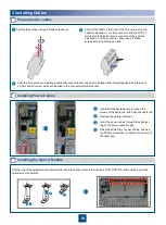
Page 14: ...14 Installing the OSN 810 on an IFS06 f 2 Installing Chassis Install the OSN 810 on the lower level from left to right ...

Page 15: ...ptional When the ambient temperature is equal to or higher than the lowest operating temperature of the OSN 810 and at least 10 C 10 F lower than the highest operating temperature of the OSN 810 repeat the preceding steps to install the OSN 810 on the higher level ...

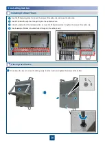
Page 16: ... screws from the chassis and pull the levers outwards and lift them upwards Connect the OT terminal at one end of the PGND cable to the ground terminal at the OSN 810 bottom and the OT terminal at the other end to the external ground bar Indicator WDM side port power port Client side port ...

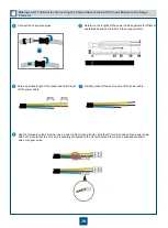
Page 17: ...mm 0 30 40 70 80 mm 0 30 40 70 80 mm 0 30 40 70 80 mm 0 30 40 70 80 Use the cable diagram label in the cover plate of the cabling cavity of the OSN 810 to measure and determine the length of jacket to be stripped off each wire of the power cable C A B A Cord end terminal B Insulation layer C Conductor Insert the conductors of the peeled cable into the cord end terminal A and make the conductors of...

Page 18: ... connector Then use a Phillips screwdriver to tighten the screws Prepare power cables c Installing Power Cables d Use the Phillips screwdriver to loosen the screws of the cable clip and open the cable clip Remove the waterproof block Insert the power cables through the silica gel ring to the power cable troughs Close the cable clip of power cables and use the Phillips screwdriver to tighten the sc...

Page 19: ... B 6 Junction part 7 Optical cable Outer diameter of the break out cable Outline drawing A mm 0 20 0 05 L1 mm 0 05 0 1 L2 mm 0 8 0 1 D mm 2 8 0 1 Material Stainless steel Only the junction part and break out cable have metal parts The lengths of the break out cables on the two sides of the equipment are different On the OptiX OSN 810 the length of the break out cable is 30 mm If the customized fib...

Page 20: ...illips screwdriver to loosen the screws of the cable clip and open the cable clip Close the cable clip of the installed cables and use the Phillips screwdriver to tighten the screws of the cable clip Insert waterproof blocks into vacant cable troughs in the cabling cavity Insert the fibers through the silica gel ring into the optical module g f 3 Installing Cables ...

Page 21: ...m of the chassis are sealed 4 Cables are routed according to the engineering documents 5 Cables are not damaged or broken there are no joints on cables and cable connectors are inserted correctly and firmly 6 Information on cable fiber labels is correct clear and neat 7 The fibers routed outside the chassis are placed in tubes or troughs and are not squeezed 8 The bend radius of fibers is 40 mm or...

Page 22: ...GND Resistance Between NEG and RTN Resistance Between NEG and PGND Resistance Between RTN and PGND 10 Ω Indicator Whether the Indicators Are Steady Green Normal State Abnormal State STAT SRV LINE CPRI Yes No Power off the chassis immediately and power on the chassis again after the fault is rectified 2 Checking Power Supply Before Power On ...

Page 23: ... the OSN 810 Attach the conversion bracket of the AC DC power module onto the rear panel of the OSN 810 and use the M6 inner hexagon torque screwdriver to tighten the captive screws on the attachment plate to 5 N m 44 25 lbf in Attach the AC DC power module onto the conversion bracket and use the M6 inner hexagon torque screwdriver to tighten the four captive screws on the AC DC power module to 5 ...

Page 24: ...C Power Module Install the conversion bracket removed from the rear side of the OSN 810 on the side of the OSN 810 Disassemble the filler panel on the bottom right of the AC DC power module using an M4 Phillips screwdriver Install the surge protector at the position for filler panel on the AC DC power module and tighten the two captive screws using an M4 torque screwdriver to 1 4 N m Disassemble t...

Page 25: ...he PGND cable of the AC DC power module Strip the specified length of the sheath off the power cable to be connected to the OSN 810 to expose the intact shield layer Open the cabling cavity of the OSN 810 and the cable clip on the power cable trough Insert the power connector at the other end of the output power cable of the AC DC power module into the power port of the OSN 810 One end of output p...

Page 26: ... cables are insulated Unit mm Use the cable diagram label in the cover plate of the cabling cavity of the AC DC power module to measure and determine the length of jacket to be stripped off each wire of the power cable C A B A Cord end terminal B Insulation layer C Conductor Insert the conductors of the peeled cable into the cord end terminal A and make the conductors of the cable to be flushed wi...

Page 27: ...aking an OT Terminal for Connecting the Power Cable of the AC DC Power Module to the Surge Protector d Cut each cable to a length suitable for the actual cable routing If the power cable is longer than or equal to 5 m cut the corrugated pipe into pieces each with a length of 5 m If the cable is shorter than 5 m cut the corrugated pipe based on the actual length of the power cable Route the power c...

Page 28: ...rimping tool to crimp the OT terminal and pull the power cable with 30 N Ensure that the core wire is securely connected to the OT terminal and there are no exposed conductor wires or copper wires Making an OT Terminal for Connecting the Power Cable of the AC DC Power Module to the Surge Protector d Determine the lengths of the power cable segments for different operations based on the label on th...

Page 29: ...loosen the screws on the cable clips and open the cable clips Use an M5 Phillips screwdriver to loosen the three screws on the cover plate of the cabling cavity of the AC DC power module and open the cover plate Use an M5 Phillips screwdriver to loosen the screws on the surge protector and open the cover plate to a 120 position ...

Page 30: ...e OT terminal of the brown wire to the L2 port the OT terminal of the blue wire to the N2 port and the OT terminal of the green yellow wire to the ground terminal 1 Power cable for connecting the AC DC power module to the surge protector 2 Power cable for connecting the surge protector to the external power supply device Installing the Power Cable for Connecting the Surge Protector to the External...

Page 31: ...el on top of the cable when cabling is done horizontally Attach the identification label to the right side of the cable when cabling is done vertically Closing the Cover Plate g Close the cover plate of the surge protector Close the cover plate of the cabling cavity of the AC DC power module and use an M5 torque screwdriver to partially tighten the screws on the cover plate in the sequence shown i...

Page 32: ...l needs to face to the right If a cable is routed horizontally the label needs to face downwards Optical fiber Label Fold to the right Fold upwards Optical fiber Optical fiber HUAWEI TECHNOLOGIES CO LTD Huawei Industrial Base Bantian Longgang Shenzhen 518129 People s Republic of China www huawei com ...

Reviews: